 A micro-controller 24FC1025 EEPROM is a single integrated circuit
, commonly with the following features:
central processing unit - ranging from small and simple 4-bit processors to complex 32- or 64-bit processors
volatile memory (RAM) for data storage
ROM, EPROM,
EEPROM or Flash memory for program and operating parameter storage
discrete input and output bits, allowing control or detection of the logic state of an individual package pin
serial input/output such as serial ports (UARTs)
other serial communications interfaces like I²C, Serial Peripheral Interface and Controller Area Network for system interconnect
peripherals such as timers, event counters, PWM generators, and watchdog
clock generator - often an oscillator for a quartz timing crystal, resonator or RC circuit
many include analog-to-digital converters, some include digital-to-analog converters
in-circuit programming and debugging support.
An external EEPROM is useful when trying to store data. In addition to storing much more data than is available on the 18F4520 PIC, an EEPROM stores the data even when power is removed and can then be collected at a later time. Storing large amounts of data over time is especially beneficial once communication can be made between the PIC and Matlab. Using the serial function in Matlab, the data can be obtained and then analyzed.
In this project, we used the PIC to log data from an analog input onto an
EEPROM and then later sent the data back from the
EEPROM to Matlab to plot. For our lab, we worked with a
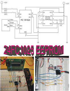
24FC1025 EEPROM whose data sheet can be found here. Additionally, we established serial port connection between the PIC microcontroller and Matlab using the RS232. Our project also made use of two buttons. The first button tells the PIC to begin collecting data points from the analog input and storing the data onto the
EEPROM. The second button tells the PIC to send the data from the
EEPROM to Matlab.
Diagram for interfacing a 24FC1025 EEPROM to the 18F4520 PIC. Below the diagram are photos of the circuit layout.
For more details regarding pin assignments for the
EEPROM, see here.
/*
Upon pressing button 1, take 1000 data values from AN0 and save to
EEPROMUpon pressing button 2, wait for Matlab response, then output all data points from EEPROM
*/
#include <18f4520.h>
#fuses HS,NOLVP,NOWDT,NOPROTECT
#use delay(clock=40000000)
#use i2c(MASTER, FAST, SCL=PIN_C3, SDA=PIN_C4, FORCE_HW) // use hardware i2c controller
#use rs232(baud=9600, UART1) // Set up PIC UART on RC6 (tx) and RC7 (rx)
#define EEPROM_WR 0xA0 // Define initial EEPROM write address block (See EEPROM data sheet)
#define EEPROM_RD 0xA1 // Define initial EEPROM read address block (See EEPROM data sheet)
int button1, button2, data_rx = 48; // Initialize variables
int16 i, temp, value, address = 0, data;
void seq_write(int16 address, int16 data)//Writing to the EEPROM function
{
i2c_start();
i2c_write(EEPROM_WR);
i2c_write(address>>8);
i2c_write(address);
i2c_write(data);
i2c_stop();
delay_ms(5);//Delay time needed in order to allow EEPROM to write data from buffer to memory sector
}
int16 seq_read(int16 address)// Reading from the EEPROM function
{
i2c_start();
i2c_write(EEPROM_WR);
i2c_write(address>>8);
i2c_write(address);
i2c_start();
i2c_write(EEPROM_RD);
value = i2c_read(0);
i2c_stop();
return(value);
}
void main() //Main Function
{
setup_adc_ports(AN0); //Setup Analog Inputs
set_adc_channel(0);
setup_adc(ADC_CLOCK_INTERNAL);
while (TRUE)
{
button1 = input(PIN_D0); // Button one is pressed when the user wants to write to the EEPROM
button2 = input(PIN_D1); // Button two is pressed when the user wants to read from the EEPROM and send the data to Matlab
if (button1 == 1) {
output_high(PIN_D0);//LED is turned on to show that writing to the EEPROM has begun
address = 0x00;
for (i=0; i<1000; i++){
data = read_adc();//Read in data from analog input (In this case it was attached to a function generator)
seq_write(address, data); // Send data from analog input to write function
address++; // Increment up the address location on the EEPROM for the next time it writes something
}
output_low(PIN_D0); // LED is turned off to show that writing to the EEPROM is complete
}
if (button2 == 1) {
address = 0x00; // start at the first address location
while (data_rx == 48) {
output_high(PIN_D1);
if (kbhit()){
data_rx = fgetc();
temp = seq_read(address); //read data from adress location
printf("%lu \r",temp); // sends data to serial port
address++; // increment up the address so it can read from the next data sector
}
button1 = input(PIN_D0);
if (button1 == 1){
output_low(PIN_D1);
data_rx = 48; // 48 is the ASCII Code for integer '0'
delay_ms(500);
break;// Basically break from this loop if user presses the first button
}
}
data_rx = 48; // 48 is the ASCII Code for integer '0'
}
}
}
Matlab Code
%Brandon Robins, Neil Tiwari and Jenny Yong
%serialcom.m
%Construct serial port object, then send confirmation for EEPROM data
%deletes any serial port objects that exist in memory
delete(instrfind)
%Define serial COM Port
s1 = serial('COM8');
%Open the com port
fopen(s1);
set(s1,'Terminator','CR');
%Length of data points to be retrieved from EEPROM
final = 1000;
%For loop for retrieving data from the EEPROM
for ii = 1:final
if ii ~= final
%Send EEPROM "0" to signal that a data point should be sent
fprintf(s1,'%s','0')
%Get data point from eeprom
x(ii) = fscanf(s1,'%g');
else
%At the very last data point send EEPROM "1" to terminate the
%sending process
fprintf(s1,'%s','1')
% Get final data point from EEPROM
x(ii) = fscanf(s1,'%g');
end
end
%Close serial port
fclose(s1);
%Delete serial port object
delete(s1);
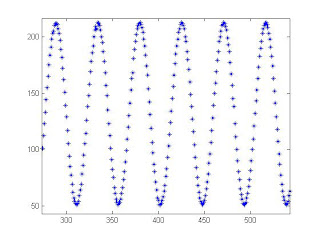
%Plot retrieved data
plot(x)
To operate the EEPROM, PIN1 and PIN2, A0 and A1 are set to ground. PIN3, A2 is connected to high for normal operation. PIN4, Vss is used to ground the chip. PIN5, SDA is the serial data line and is connected to RC4 (PIN23) on the PIC. PIN6, SCL is the serial clock line which is connected to RC3 (PIN18) on the PIC. PIN7, WP is the write protect line. For our purposes, we set PIN7 to ground to disable this function and allow us to rewrite our data onto the EEPROM. PIN8, Vcc is connected to high to power the chip.
In order to connect our PIC to Matlab, we use the RS232. As mentioned here, we connect the black wire to ground, the orange wire to pin 26, RC7 and the yellow wire to pin 25, RC6.
Additionally, we used two buttons connected to digital inputs on the PIC which dictate when to collect and store data and when to send the data to Matlab.
code matlab
%Brandon Robins, Neil Tiwari and Jenny Yong
%serialcom.m
%Construct serial port object, then send confirmation for EEPROM data
%deletes any serial port objects that exist in memory
delete(instrfind)
%Define serial COM Port
s1 = serial('COM8');
%Open the com port
fopen(s1);
set(s1,'Terminator','CR');
%Length of data points to be retrieved from EEPROM
final = 1000;
%For loop for retrieving data from the EEPROM
for ii = 1:final
if ii ~= final
%Send EEPROM "0" to signal that a data point should be sent
fprintf(s1,'%s','0')
%Get data point from eeprom
x(ii) = fscanf(s1,'%g');
else
%At the very last data point send EEPROM "1" to terminate the
%sending process
fprintf(s1,'%s','1')
% Get final data point from EEPROM
x(ii) = fscanf(s1,'%g');
end
end
%Close serial port
fclose(s1);
%Delete serial port object
delete(s1);
%Plot retrieved data
plot(x)


 Electrically erasable programmable read-only memory (EEPROM) chips are similar to PROM devices, but require only electricity to be erased. Architecture or status, performance, power characteristics, and packaging information are all important parameters to consider when searching for EEPROM memory chips.

