Selasa, 28 Juni 2011

DTMF


Dual-tone multi-frequency (DTMF) signaling is used for telephone signaling over the line in the voice-frequency band to the call switching center. The version of DTMF used for telephone tone dialing is known by the trademarked term Touch-Tone, and is standardised by ITU-T Recommendation Q.23. Other multi-frequency systems are used for signaling internal to the telephone network.
DTMF is the global standard for audible tones that represent the digits on a phone keypad.

With touch-tone land-line phones, pressing a key on the dialpad generates the corresponding DTMF tone for that key. The land-line phone system can then "listen" and decode that tone to determine which key was pressed, enabling dialing.

Mobile phone networks use digital signals instead of DTMF for direct dialing, but DTMF is still used over mobile phones to navigate automated systems such as phone menus, and for secondary dialing, such as using a calling card.

Each DTMF "tone" is actually two tones - a low-frequency tone and a high-frequency tone - combined. (Hence the name "dual tone multi-frequency".) Looking at the standard phone keypad as a grid, the low tone corresponds to the row, while the high tone corresponds to the column.

DSC software utilizes DTMF signaling in our award winning computer telephony software applications.

IVR software from DSC uses DTMF signaling as the primary user communication method. Calls are processed using our automatic call distribution system which determines the called number and transfers this call to an agent hunt group.

Call center agents or workstations are identifed to the phone system and placed in various user groups. As a call is received, the DNIS of this call is used to lookup the agent group associated with this DNIS. The next available agent in this group is determined and the call is routed to this workstation.

DTMF processing is just one of the many features of our computer telephony integration and IVR software. This rich set of phone software library routines enables application programs to control a phone system.

CTI software lets you increase your call processing center's productivity, enhance customer service and reduce costs by combining the capabilities of our call center phone system with the custom functionality of your Windows, Unix or Web applications.

Data collected by our ACD (Automatic Call Distribution) or IVR (Interactive Voice Response) systems can be passed to your existing PC, Unix or Web applications through our CTI software.
READ MORE - DTMF

VCO


Oscillators are devices that are used to generate repetitive signals. They produce output signals without an input signal. There are two major types of electronic oscillators: harmonic oscillators and relaxation oscillators. Harmonic oscillators produce sine wave outputs. Relaxation oscillators produce square wave, rectangular wave, and sawtooth outputs. For both types of devices, an active component (normally, in the feedback loop) determines the frequency of oscillation. This active component can be either an electronic circuit or a crystal.

Voltage-controlled oscillators (VCO) and voltage-controlled crystal oscillators (VCXO) change the frequency in direct proportion to a control voltage. Basic crystal oscillators (XO) do not. Temperature-compensated crystal oscillators (TCXO) use a thermistor network to generate a correction voltage to reduce frequency deviations over temperature. Oven-controlled crystal oscillators (OCXO) use temperature control circuitry to hold the crystal and its circuitry at a precise, constant temperature. Other oscillator types include voltage-controlled, temperature-compensated crystal oscillators (VCTCXO); oven-controlled, voltage-controlled crystal oscillators (OCVCXO); and digital, temperature-compensated, crystal oscillators (DTCXO). Microcomputer-compensated crystal oscillators (MCXO), rubidium crystal oscillators (RbXO), voltage-controlled SAW oscillators (VCSO), dielectric resonator oscillators (DRO), and simple packaged crystal oscillators (SPXO) are also available.

There are several packaging methods and form factors for oscillators. Surface mount technology (SMT) adds components to a printed circuit board (PCB) by soldering component leads or terminals to the top surface of the board. By contrast, through hole technology (THT) mounts components by inserting component leads through holes in the board and then soldering the leads in place on the opposite side of the board. Oscillators that are modules or boards are also available. Connectorized devices attach with coaxial or radio frequency (RF) connectors. Waveguide assemblies consist of a hollow metallic conductor with a rectangular, elliptical, or circular cross-section. Some conductors contain solid or gaseous dielectric materials. Most are used in microwave waveguide systems.

Performance specifications for oscillators include oscillation frequency, frequency tolerance, total frequency stability, resistance, operating temperature and supply voltage. Oscillation frequency is a nominal frequency value. Frequency tolerance or frequency error is the allowed, stated deviation from the nominal oscillation frequency. Typically, frequency tolerance is expressed as a percentage. Total frequency stability is the maximum frequency deviation from the nominal value for all conditions, including supply voltage. This amount is usually expressed in parts per million (ppm). Operating temperature is the full-required range of ambient operating temperatures. Typical supply voltages include 1.8 V, 2.5 V, 3.3 V, 5.0 V, 12.0 V, and 15 V.

Oscillators vary in terms of output type. Circuits with transistor-transistor logic (TTL) use a 5 V power supply. TTL signals are "low" when between 0 V and 0.8 V with respect to the ground terminal and "high" when between 2 V and 5 V. A complementary metal-oxide semiconductor (CMOS) is a low-power technology that can achieve high switching speeds. High-speed CMOS (HCMOS) provides faster switching speeds than conventional CMOS. Emitter coupled logic (ECL) is an extremely high-speed logic that consumes a great amount of power. Variants include positive emitter coupled logic (ECL) and low voltage, positive emitter coupled logic (LVPECL). Low voltage differential signaling (LVDS) is also available.

There are several important features and standards for oscillators. Restriction of Hazardous Substances (RoHS) is a European Union (EU) directive that requires all manufacturers of electronic and electrical equipment sold in Europe to demonstrate that their products contain only minimal levels of the following hazardous substances: lead, mercury, cadmium, hexavalent chromium, polybrominated biphenyl and polybrominated diphenyl ether. RoHS will become effective on July 1, 2006. By definition, lead-free devices contain less than 1000 ppm lead by weight. Some oscillators are suitable for programmable devices. Others are designed for military applications.
READ MORE - VCO

Data Terminal Equipment


Digital delay generators produce pulses at precise, programmed intervals to trigger devices under test. They are also used for gating, timing, triggering, and syncing. Basic digital delay generators are single-channel devices. More complex products with multiple channels are also available. Both types are similar to pulse generators, but have a much finer timing resolution and a much lower time delay and width-jitter. Sophisticated devices that combine the functions of digital delay generators and pulse generators may provide independent amplitude polarity and level control for each output. Some digital delay generators are used to produce edges to trigger devices. Others provide precise delays and width for grating.

Selecting digital delay generators requires an analysis of product specifications such as timing delays and widths. Percent accuracy, time base, root mean square (RMS) jitter, and trigger mode are also important considerations. There are six choices for trigger mode: burst, continuous, external trigger, external gate, duty cycle, and single shot. With burst mode, any channel may provide a burst of pulses at the internal rate, and the number of pulses may vary by channel. Duty-cycle digital delay generators set timing events at ON for M pulses and OFF for N pulses. Devices with an external trigger or external gate trigger-mode carry parameters such as rate, insertion delay, threshold, trigger slope (rising or falling edge), and impedance. Single-shot digital delay generators may have a pushbutton that provides a single trigger.

Many digital delay generators include a computer interface with an RS232, GPIB, USB or Ethernet connection. RS232 is a serial interface between data terminal equipment (DTE) and data communications equipment (DCE) that uses a binary data interchange. The general-purpose interface bus (GPIB) is designed to connect computers, peripherals and laboratory instruments so that data and control information can pass between them. Universal serial bus (USB) is a 4-wire, 12-Mbps serial bus for low-to-medium speed peripheral device connections. Ethernet is a local area network (LAN) protocol that uses a bus or star typology and supports data transfer rates of 10 Mbps. Digital delay generators that use other types of computer interfaces are also available.
READ MORE - Data Terminal Equipment

TLC 555


TLC 555
Most modern energy meter have one or more LEDs which blink at a rate directly related to the energy used. The one above has two of them : one pulses at 1000 pulses per active kWh, the other one pulses at 1000 pulses per reactive kWh. I dealed with the active power only, event though I’m billed partially for reactive power also.

The idea is to collect the blinks of the LEDs in 5 minutes blocks. Twelve groups of 5 minutes-worth counts give an hour, then data are collected around 24 hours.


I used Processing to read to read the LED through a webcam and detect and collect the blinks.

Processing and its video library is the most obvious choice to me as I’m not much of a high-level programmer. Processing is well supported and gives instant gratification. It also runs on a variety of platforms, including my little Acer Aspire One where I managed to have processing run some time ago.

Grabbing the camera image is straighforward with processing : had to install vdig (vs 1.0.1) as instructed in the processing support forum and Apple’s Quicktime 7 which is the essential part to grab the video Everything went smooth, on my desktop at least. I couldn’t have it running on my Aspire One as vdig of course doesn’t run on it, and would have had to use a different library.

That said, I wrote a quick ‘sketch’ in Processing to grab the camera, select with the mouse the “hot spot” of the meter (the LED) to minimize interference from the reactive power LED and ambient lights reflection. The code also represents visually the energy used in 5-minutes chucks over the 24 hours.

This is what is seen in Processing through the web cam. The image is upside-down because the camera is. But of course it doesn’t matter.
READ MORE - TLC 555

Senin, 20 Juni 2011

Electrical inductance sensors


Electrical inductance sensors are non-contact devices that measure the inductance of an electrical component or system. They consist of a wire loop or coils and are relatively inexpensive. Inductance, the property of a circuit or circuit element to oppose a change in current flow, refers to the capacity of a conductor to produce a magnetic field. The standard unit of inductance is the Henry (H). Because the Henry is a large unit, electrical inductance sensors often measure inductance in microhenry (µH) or millihenry (mH) levels.

Electrical inductance sensors contain a nickel-iron core shaft that rotates within the coil around the material. The inductance measured by an electrical inductance sensor depends on the number of turns in the coil, the type of material around which the coil rotates, and the radius of the coil. With the rotation of the shaft, displacement occurs within the coil and generates inductance. This displacement produces signals that can be measured by an inductance meter and recorded. Most inductance meters are digital, hand held devices suitable for measuring inductance of very low value. The results of the inductance calculation can be plotted as a graph for future study.

Selecting electrical inductance sensors requires a careful analysis of product specifications and application requirements. Most electrical inductance sensors have a standard accuracy variance of less than 0.5% when measured on full scale. For best results, an electrical inductance sensor should be able to generate an output signal of at least 4-20 mA. Typically, a sensor’s measurement range is approximately 30% of the coil diameter. For high precision measurements, the thickness of the coil should be at least 0.025 inches (in.).

Electrical inductance sensors are used in many different applications. Some electrical sensors are used in the automotive industry and the power industry. Other electrical sensors are used in constructing planar transformers, generating electrical magnetic fields, and monitoring the inductance of an electrical component. Electrical sensors such as electrical inductance sensors are widely used for detecting the presence of electrical voltage in equipments.
READ MORE - Electrical inductance sensors

Electronics is an engineering


Electronics is an engineering discipline that involves the design and analysis of electronic circuits. Originally, this subject was referred to as radio engineering. An electronic circuit is a collection of components through which electrical current can flow or which use electromagnetic fields in their operation.

The electronic circuit design and analysis rests primarily on two Kirchoff's laws in conjunction with Ohm's law modified for AC circuits and power relationships. There are also a number of network theorems and methods (such as Thevenin, Norton, Superposition, Y-Delta transform) that are consequences of these three laws. In order to simplify calculations in AC circuits, sinusoidal voltage and current are usually represented as complex-valued functions called phasors. Practical circuit design and analysis also requires a comprehensive understanding of semiconductor devices, integrated circuits and magnetics.

Electrical engineering (sometimes referred to as electrical and electronic engineering) is a semi-professional and professional engineering discipline that deals with the study and/or application of electricity, electronics and electromagnetism. The field first became an identifiable occupation in the late nineteenth century with the commercialization of the electric telegraph and electrical power supply. The field now covers a range of sub-studies including those that deal with power, electronics, optoelectronics, digital electronics, analog electronics, computer science, artificial intelligence, control systems, electromagnetics, photonics, signal processing and telecommunications.

The term electrical engineering may or may not encompass electronic engineering. Where a distinction is made, electrical engineering is considered to deal with the problems associated with large-scale electrical systems such as power transmission and motor control, whereas electronic engineering deals with the study of small-scale electronic systems including computers and integrated circuits. Another way of looking at the distinction is that electrical engineers are usually concerned with using electricity to transmit energy, while electronics engineers are concerned with using electricity to transmit information. William Gilbert, with his 1600 publication of De Magnete, was the originator of the term "electricity" and many regard him as the father of electrical engineering or of electricity.
READ MORE - Electronics is an engineering

Minggu, 19 Juni 2011

multi layer ceramic capacitors (MLCC)


A capacitor is one of three passive devices and its main function is to store electric charge. There are aluminum electrolytic capacitors, tantalum electrolytic capacitors, ceramic capacitors, electrolytic capacitors, and others. Capacitors can be simply divided into fixed capacitors, variable capacitors, and chip capacitors. Ceramic capacitors can be divided into single layer ceramic capacitors (disk ceramic capacitors) and multi layer ceramic capacitors (MLCC).

MLCCs have compact size, which is required for modem electronic devices, and they also provide the following advantages: high capacity, low inner inductance that makes them suitable for high frequency, high insulation, low current leakage, high stability because the inner electrode is protected by ceramic and not easily effected by the environment, high thermal resistance, non polarity, and surface mount. Because of the features mentioned above, MLCCs are widely applied in cellular phones and laptop computers, which need smaller sized capacitors.

The size of the MLCC has to be smaller and smaller because electronic devices are becoming more and more compact. In order to maintain large capacitance, more layers inside the MLCC are necessary. Miniaturization of material particles and controlling of layers have to be considered in the manufacturing process. Because the manufacturing temperature is as high as 300-400 degree C, one must take thermal resistance into consideration when selecting materials. These points mentioned above indicate that the manufacturing processes, selection of material, and packaging are becoming more and more difficult. Another type of porous micro-structure capacitor uses a three-dimensional structure such as multiple grooves to increase the surface area of electrodes A thin film process is then used to reduce the thickness in order to obtain a micro structure capacitor with high capacitance. However, it is very difficult to have a layer of thin film coated on the pore with high aspect ratio (depth/width ratio). That is to say, a regular etching process is not able to obtain deep etching so the quality of the product is not uniform. When the aspect ratio of a micro structure pore increases, the coating process usually ends up creating thicker coating in the opening of the pore and thinner coating in the bottom of the pore, or the opening is blocked so the bottom portion is not coated at all.

These conventional micro-structure capacitors that put emphasis on high porosity and high aspect ratio for obtaining high electrode surface area are always three-dimensional, so the capacitance increases as the electrode surface area increases. However, pore size is not very uniform because it is not well controlled, so the capacitance can't be easily controlled. Because very deep pores are required to obtain high capacitance, the coating process usually produces a thicker layer in the opening and thinner layer in the bottom of the pores. The thin-film layer generated by a regular sputtering instrument is unable to achieve good coverage over the pores with high aspect ratio.
READ MORE - multi layer ceramic capacitors (MLCC)

Rabu, 15 Juni 2011

Attic Breeze fans are made with all metal construction


Attic Breeze offers both the most durable and powerful solar powered ventilation products available. Using only the highest quality parts and materials, Attic Breeze manufactures solar attic fans and solar powered ventilation products that will stand up to the harshest weather conditions time after time. Attic Breeze fans are not the cheapest solar powered attic fans on the market, but they are most definitely the best.

What makes Attic Breeze the best fan on the market?

Attic Breeze fans are made with all metal construction, not plastic like most other fans. In addition, the seams are welded instead of being fastened with pop rivets (which can wear loose from vibrations and leak or crack). Corrosion resistant zincalume alloy and stainless steel materials are used to ensure weather resistance and durability.

Attic Breeze uses high quality monocrystalline solar cells which are more efficient and longer lasting then industry standard polycrystalline cells. In addition, Attic Breeze builds the only 25 watt solar powered attic fans on the market. Capable of moving up to 1550 CFM, it typically takes two or three of the competitors fans to achieve the same performance as one Attic Breeze fan.

Attic Breeze fans include a thermal switch standard on all products. This switch allows the fan to shut down when attic temperatures fall below the preset range. The fan can also be opperated without the switch in northern climates to help control moisture during the winter.

Attic Breeze fans feature ultra quiet operation. This fan produces less then 1 sone (30 dB).

Attic Breeze fans are made in the USA. In fact, they are made in Texas where thunderstorms carry large hail and high winds. With a rugged construction and high quality materials, this fan is built to last a lifetime. Attic Breeze has so much confidence in this fan that it comes with an industry best Manufacturer's Lifetime Warranty.

olar attic fans offer an environmentally friendly and economical solution to summer time cooling problems resulting from attic heat penetrating your home's insulation. During the summer, attic temperatures can soar to over 150°F, keeping your attic hot throughout the day and well into the night. The higher the temperature of your attic, the less effective your attic insulation will be at stopping heat from entering your home.

Installation of a solar attic fan on your home minimizes the amount of heat entering through the attic by reducing your attic temperature. By minimizing the amount heat entering your home, you will save money on your summer cooling bill and make your house feel more comfortable (see diagrams

Attic Breeze residential and commercial solar powered ventilation fans offer many advantages over competitive products:
Zincalume alloy vent housing (superior corrosion resistance for costal climates), comes standard with all Attic Breeze ventilation products
Powerful 14 inch aluminum fan capable of moving over 1550 CFM of airflow (energy efficient design and ultra quiet operation)
Models available with solar panel either directly attached to attic vent unit or with remote mounted solar panel options
More options available than any other competitive product
All solar attic vent units are manufactured with thermal switch included at no additional charge ($20-$30 charge with other manufacturers!)
Attic vent units available in heavy-duty powder coated finishes (black, brown, or gray), or unpainted zincalume alloy.
High-efficiency, industrial grade monocrystalline solar panels, made with high strength tempered glass
Durable all metal design and construction capable of withstanding extreme weather conditions and high winds
Offers a "green building solution" for your home, warehouse, farm, or workshop design
Products may qualify for incentives in your area reducing purchase and installation costs by several hundred dollars
All residential and commercial products are covered by the best warranty available in the the industry
READ MORE - Attic Breeze fans are made with all metal construction

LPC2468 ARM7TDMI-S mode USB

LPC2468 ARM7TDMI-S mode USB
LPC (short for Lars Pensjö C) is an object-oriented programming language derived from C and developed originally by Lars Pensjö to facilitate MUD building on LPMuds. Though designed for game development, its flexibility has led to it being used for a variety of purposes, and to its evolution into the Pike programming language.

LPC syntax places it in the family of C-like programming languages, with C and C++ its strongest influences.

Discover the performance of the LPC2468 ARM7TDMI-S based microcontroller with the LPC-Stick! The LPC-Stick is a small modular evaluation kit with optional extension boards. The LPC-Stick package provides target hardware with the LPC2468 microcontroller from NXP, external SRAM, user pins and LEDs for applications use. Combined with the proven USB debugger device connection and the non-limited HiTOP development tools, the LPC-Stick allows full access to all chip features, debugging and programming.

To provide access to the most external capabilities of the LPC2468 chip, the Stick allows to connect various extension boards via an 80 pin extension connector. The toolset does not require any power supply or cables – just install the tools and run the demo application! Make your first steps with the demo application and the graphical user interface: Debugging and user communication via USB at the same time!

The LPC-Stick package contains:
LPC-Stick hardware with LPC2468 microcontroller (ARM7TDMI-S CPU core + Ethernet, USB/OTG, CAN), Extension connector, User LEDs, user IO…
Stick demo application with GUI control software
HiTOP5 IDE and debugger
GNU C/C++ compiler
Tasking VX-Toolset (limited evaluation version)
USB interface for debugging, programming and virtual COM port for user application
CD containing toolchain and useful information and datasheets

To fit future requirements Hitex decided to give the user the best possible access to the LPC2468 features. Providing a high number of pins the designers implemented the LPC extension connector.
READ MORE - LPC2468 ARM7TDMI-S mode USB

Miniature Circuit Breaker (MCB) is a device designed to protect a circuit's

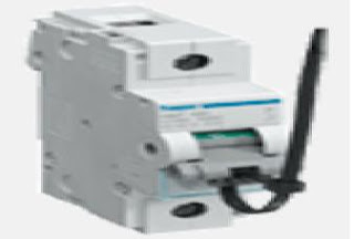
Miniature Circuit Breaker (MCB) is a device designed to protect a circuit's wiring from the serious damage which would be caused if it has to carry a current which is too high for the diameter of its wires. Such a current could easily heat up the wires so much that their insulation melts. If that situation were allowed to develop further it would soon cause the wires in a cable to short out and to burn so hot that they could easily cause a house fire.

Before circuit breakers were invented, simple wire fuses were used: the wire in the fuses was deliberately made much thinner than the wires in the circuits they were intended to protect. Thus, if a fault condition occured, as the current in the circuit grew higher and higher, a point would be reached at which the thin wire of the fuse would get so hot that it would melt - all safely contained within the body of the fuse - and thus break the flow of current in the circuit it was protecting.

The problem with fuses is that - depending on their design, as some are faster-acting than others - it can take a significantly longer amount of time for them to operate compared with today's very-fast-acting circuit breakers. That fact means that, if a circuit overload current fault condition occurs, considerable damage can still occur both to the circuit wiring and/or to the unit it is supplying with power. Then, after the fault condition has been fixed, the melted or "blown" fuse wire in a rewireable type of fuse has to be replaced or - if it is a "disposable cartridge" fuse - the blown fuse cartridge has to be thrown away and replaced by a new one. A circuit breaker, if it is still in good condition, only needs to be reset.

It is no joke to say if it is still in good condition...! One more fact needs to be mentioned: a significant design feature built into today's circuit breakers is their ability to "self-destruct on a crowbar fault ". A "crowbar fault" is a very serious overload condition, so bad that it would cause many thousands of amps to flow, just as if someone had thrown down a heavy metal crowbar tool onto power lines to connect both hot and neutral wires... Such a fault condition can only be stopped by what is the ultimate fail-safe function of all modern circuit breakers: by using electro-magnetic technology similar to that of a simple relay, they are designed to self-destruct at least as fast as - if not faster than - the fastest acting fuses!

In brief, wherever electrical equipment - and the wiring which supplies it - need to be protected from overload current fault conditions then:

a) if the physical space available allows circuit breakers to be installed, and

b) if the higher initial costs of deploying circuit breakers can be afforded

then it is significantly better to deploy circuit breakers instead of fuses.


The range of multi pole MCB’s from 80A to 125 A are equipped with strong terminals. They present better grip on the cable. In particular, the MCB’s 80, 100 and 125 A are equipped with the 'tightening compensation system'. True Hager innovation, this system compensates for the deformation of the cables related to their ageing and vibration, thus prolonging the effectiveness of initial tightening torque.


This range makes it possible to combine product with RCD add-on-block, simple, fast and secured.
1. Assembly, 2. Connection, 3. Locking
The assembly of the RCD add-on-block is carried out in three steps. Simple and rapid for a secured assembly: it is a Hager innovation.


125A MCB is suitable for residential, commercial and industrial installations with high breaking capacity.Protection of installations is guaranteed by the 10 KA or 15KA breaking capacity defined according to IEC60898-1 and IEC60947-2 standards.


MCB can be locked in the « Off » position by the integrated locking facility on the handle. This lock can be inserted with a 2.5 - 3.5 mm plastic cable tie where you can fit a warning card if necessary and allows a safer working environment for all personnel.
READ MORE - Miniature Circuit Breaker (MCB) is a device designed to protect a circuit's

Aquatic Energy’s solution is to offer industry-leading


In the past five years, the price of food and fuel have risen to new heights, accompanied by mounting climate and food pressures.
Aquatic Energy’s solution is to offer industry-leading, affordable algae biotechnology that can replace fossil fuels, boost nutrition in foods and provide essential ingredients for vitamins, cosmetics and other life-enhancing products.

That’s because algae are the fastest-growing plants in nature, yielding more usable oil and meal than any traditional crops, including soybean and corn. Plus, algae can be harvested quickly, efficiently and without producing particulate, pollution or toxins.

To make the most of algae, Aquatic Energy’s world-class team of commercial algae experts and business leaders apply their best thinking and skills, backed by the insights and experience of our scientific, governmental and energy advisors.

Together, we’ve created the right algae solution. It combines the right strategy, species, science and strategic location to produce algae with the right scale — in a way that’s sustainable. The result is a product that is more cost-effective than other biofuel crops and the algae produced by our competitors.

Here’s how: We employ state-of the-art technology, using a proprietary strain of algae. The algae flourish in an ideal setting — a freshwater, open-pond farm in Louisiana. This growing environment resists disease, weeds, insects and competing strains, without displacing agricultural land or using potable water. Our production process and techniques for delivering high-quality algal oil and meal are clean and carbon neutral — yielding the largest amounts of usable algae products .

The result is a natural renewable energy source that can be used to produce the world’s fuel, human and animal food, vitamins, cosmetics and pharmaceuticals, while respecting the earth and other life forms.
READ MORE - Aquatic Energy’s solution is to offer industry-leading

condensing steam turbine


With a condensing steam turbine the vacuum to be in the condenser is already established by the turbine design. The cooling water flow is already determined based on the turbine design steam rate and the water supply temperature. When the load on the turbine is reduced the turbine inlet steam supply valve is modulated and less steam is there to condense. The condenser water flow may be reduced. If the water supply temperature changes the flow may be also changed. This is usually done automatically by adjustment of the condenser water supply control valve. The condenser vacuum controller sends the appropriate operating signal to that water valve actuator. Reducing the water flow reduces the horsepower needed by the pump motors.
The Rankine Cycle is inherently inefficient because the energy expended to evaporate the boiler water is all lost through the condenser and ends up either being discharged by evaporation in the cooling towers, by release into the river or bay, or to a cooling pond. However, if there is a need for a steam heating supply elsewhere, the heat of condensation can be utilized there. This can be the case in the winter where building heating is needed or also in a manufacturing process . A back-pressure turbine is employed and the condensing turbine cut back. This is a practice in some industrial manufacturing plants, but not in dedicated utility power plants.

Turbine, rotary engine that converts the energy of a moving stream of water, steam, or gas into mechanical energy. The basic element in a turbine is a wheel or rotor with paddles, propellers, blades, or buckets arranged on its circumference in such a fashion that the moving fluid exerts a tangential force that turns the wheel and imparts energy to it. This mechanical energy is then transferred through a drive shaft to operate a machine, compressor, electric generator, or propeller. Turbines are classified as hydraulic, or water, turbines, steam turbines, or gas turbines. Today turbine-powered generators produce most of the world's electrical energy. Windmills that generate electricity are known as wind turbines (see Windmill).

Hydraulic Turbines

The oldest and simplest form of the hydraulic turbine was the waterwheel, first used in ancient Greece and subsequently adopted in most of ancient and medieval Europe for grinding grain. It consisted of a vertical shaft with a set of radial vanes or paddles positioned in a swiftly flowing stream or millrace. Its power output was about 0.5 horsepower. The horizontal-shaft waterwheel (that is, a horizontal shaft connected to a vertical paddle wheel), first described by the Roman architect and engineer Marcus Vitruvius Pollio during the 1st century BC, had the lower segment of the paddle wheel inserted into the stream, thus acting as a so-called undershot waterwheel. By about the 2nd century AD, the more efficient overshot wheel had come into use in hilly regions. Here the water was poured on the paddles from above, and additional energy was gained from the falling water. The maximum power of the waterwheel, which was constructed of wood, increased from about 3 horsepower to about 50 horsepower in the Middle Ages.

The transition from waterwheel to turbine is largely semantic. The first important attempt to formulate a theoretical basis for waterwheel design was in the 18th century by the British civil engineer John Smeaton, who proved that the overshot wheel was more efficient. The French military engineer Jean Victor Poncelet, however, devised an undershot wheel, the curved blades of which raised efficiency to nearly 70 percent; it quickly came into wide use. Another French military engineer, Claude Burdin, invented the term turbine, introduced as part of a theoretical discussion in which he stressed speed of rotation. Benoit Fourneyron, who studied under Burdin at the School of Mines at St. Étienne, designed and built wheels that achieved speeds of 60 or more rpm (revolutions per minute) and provided up to 50 horsepower for French ironworks. Ultimately Fourneyron built turbines that operated at 2300 rpm, developing 60 horsepower at an efficiency of more than 80 percent.

Despite its remarkable efficiency, the Fourneyron turbine had certain drawbacks as a result of the radial outward flow of water that passed through it. This created problems if water flow was reduced or load removed. The British-born American engineer James B. Francis designed a turbine in which the flow was inward, and the so-called reaction, or Francis, turbine, became the most widely used hydraulic turbine for water pressures, or heads, equivalent to a column of water 10 to 100 m (33 to 330 ft). This type of turbine operates by expanding the pressure energy in the water during the flow through the blade passages, resulting in a net force, or reaction, which has a tangential component that turns the wheel.

For installations where water heads of about 90 to 900 m (about 300 to 3000 ft) were available, the Pelton wheel, named after the American engineer Lester Allen Pelton, came into use during the second half of the 19th century. In this turbine, the water is piped from a high-level reservoir through a long duct, or penstock, to a nozzle where its energy is converted into the kinetic energy of a high-speed jet. This jet is then directed onto curved buckets, which turn the flow by nearly 180 degrees and extract the momentum. Because the action of the Pelton wheel depends on the impulse of the jet on the wheel, rather than on the reaction of the expanding water, this type of turbine is also known as an impulse turbine.
READ MORE - condensing steam turbine

Selasa, 07 Juni 2011

REINFORCED OP-AMP (LM 741)

REINFORCED OP-AMP (LM 741)
Op-Amp amplifier would strengthen the reverse voltage at the input and reverse the result of strengthening it, so the output of this circuit will always have an opposite polarity input signals.

Strengthening the voltage on this circuit is specified by
The output voltage is obtained by multiplying the input voltage is known by a factor strengthening, or
Minus signs are ignored in the calculation because only show that the opposite phase output against input.

The amplifier is not turned
In this configuration the feedback is used to set the permanent strengthening of the input provided on the reverse, but given the input Vin is not flipped so that the output voltage will always be phase with the grid input voltages.
To get the tension reinforcement can be searched by the following equation
To obtain the output voltage can be found by multiplying the input voltage is known by a factor strengthening, or

Summing amplifier voltage
By using reverse amplifier circuit base and add resistors to the other input, we can make a summing amplifier reverse. Output voltage is reversed and it is equal to the algebraic sum of each input voltage multiplication with the results for the input resistor with a corresponding feedback resistor, or can be expressed as follows

Spare RF / RN (VN) in the formula above states that in such settings may have more than two entries. When all external resistor equal in value (Rf = R1 = R2 = ... = RN), the output can easily can be calculated as the algebraic sum of each input voltage, or

READ MORE - REINFORCED OP-AMP (LM 741)

Faraday's Law


Faraday's Law
The direction of the electric field at some point can be described graphically using this style. concept lines put forward by Michael Faraday in which reads:

A line of force in an electric field is a line style that was described when the tangent line at each of its point shows the direction of the electric field at that point.

Lines of force toward the exit of positive charge and the entrance to to load negative. to show the lines of force directions can be performed the experiment as follows:

Strong electric field at a point in space is proportional to the number of lines of force per unit surface area perpendicular to the electric field at that point. can be concluded that the strong electric field will feel stronger when the distance between the two charges are close together.

So the lines of force generated very tight. otherwise if the two charges are far apart, the strong electric field that is formed will be weak.

The use of electric potential can be connected with the concept of an electric field, the basics of electrical circuits as well as practical problems associated with electrical devices. to explain the definition and properties of two dots in each other and the potential difference lies in an electric field as a potential difference between two points.

Potential difference between two points is the work done per unit charge if the charge is moved. in SI units, units of electrical potential difference is the volt (abbreviated V), with 1 volt = 1 joule / coloumb. electric potential can be defined as the ratio of electrical energy to the charge that point.
READ MORE - Faraday's Law

The series Downloader / Programmer AT89S51/AT89S52


Atmel is a considerable AT89S51/AT89S52 product in the market for less than 20 thousand dollars. To start learning this type of microcontroller 89S51 we need a programmer and circuit Downloader. Programmer is a hardware device used to enter machine language program compiling our code in the microcontroller.

picture above shows the circuit diagram in system programmer interface, the power to the interface provided by the target system. The 74HCT541 ic isolate and buffer the parallel port signals. It is necessary to use the HCT type ic in order to ensure that the programmer should also work with 3V type parallel port.

Husband downloader circuit scheme can be used to program the serial devices 89S and AVR series devices are pin compatible to 8051, such as the 90S8515. For other AVR series devices the user can create an adapter board to the pin 20, 28 and 40. pin numbers indicated in parentheses according to the PC parallel port
connector.

The following are the main features of this software,

Read / write the Intel Hex file
Read the signature, lock and fuse bits
Remove / Fill the buffer memory
Verify with memory buffer
Reload current Hex File
Display buffer checksum
Programs & fuses bits of the selected key
Auto hardware detection
READ MORE - The series Downloader / Programmer AT89S51/AT89S52

Assembly source program is a program written


Assembly source program is a program written by the programmer in the form of a collection of command lines and is usually stored with the extension. ASM. assembly source programs consist of several parts: Label, Mnemonic, Operands, and feedback.

1. Label

useful in giving the name of the destination addresses, because the labeling of a better address is relative. In addition, record labels are also used as a self-program flow. To create a label, there are several requirements that must be met, where this requirement is sometimes also depends on the assembler program is used, namely:

-Must begin with the letter.
-It is not allowed the same label in one assembly program.
-A maximum of 16 characters.
-Not allowed any space character in the label.

2. Mnemonic

Mnemonic or it could be called the operation code is the code that will be done by the assembler program on a microcontroller commands or instructions that are very dependent on the type of microcontroller used. For example, to use MOVX MCS51 family, MOV, ADD and others.

3. Operand

Operand is the complement of the mnemonic, number of operands required by the mnemonic is not always the same, a mnemonic can have three, two, one or no operand at all.

4. Comments

There is absolutely no comment section in a program, but this section is very useful to explain the processes of work or specific notes on the parts of the program. Even programmers often need to recall the way the program plan.
READ MORE - Assembly source program is a program written

Light Emitting Diode (LED)


Light Emitting Diode (LED) is a diode that can remove light or light if given a voltage. Light Emitting Diode (LED) typically function as indicator lights or signal lights, Light Emitting Diode (LED) is also usually used for decorative lights. Led a variety of colors including the color: color rnerah, green, yellow, and white. In iImu Electronic Light Emitting Diode (LED) is often used as indicators, voltage indicators, inputs, outputs or the other.

Here is a picture of Light Emitting Diode (LED) and their symbols:

In the next picture we can see an example of a Light Emitting Diode (LED) along with its symbol. In a Light Emitting Diode (LED) has two feet of the polarity of the polarity of positive and negative polarity. In the Light Emitting Diode (LED) that can change colors usually have a 3 foot postive polarity is the polarity of 1, 2 and postive polarity negative polarity. The occurrence of color difference in a Light Emitting Diode (LED) in because of obstacles or resistance values ​​are different. This then resulted in changes in voltage on a Light Emitting Diode (LED).
READ MORE - Light Emitting Diode (LED)

Static Electricity Applications


Static Electricity Applications

Lightning is one example of the release of electrical charge in large enough quantities. This liberation can occur between clouds and the clouds or between cloud and earth. Why on earth? Because the earth is a place that can accommodate any size electric charge. When clouds move from one place to another to form rain, the clouds will experience a polarization due to the influence of a place on the earth's surface, usually a higher place to the surroundings. Polarization charge caused a very high potential differences that could result in sparks leap we are known by the name of lightning.

Exemption of electric charge (discharging)
When electrically charged objects, he can be in the neutralization by moving electric charge. This process is known as the discharging.

Discharging the insulating material.
Heating is an effective way in the liberation of electric charge. This happens because the heat causes the air around the material becomes ionized. Ion around the material will neutralize the electrical charge material.

Discharging the conductor material.
Electrical charge conductor material can be neutralized by connecting to earth (grounded). Conductors used to connect the material with the earth, is the electron traffic. If the material is positively charged, the electrons flow from the Earth to the material. Conversely, if negative charged materials, the electrons flow from the material to earth.

If the potential difference between two charged objects large enough then the neutralization can occur spontaneously. One example of an electric charge liberation events in large numbers is lightning. The amount of electric charge which was released then the lightning may cause damage to objects on the surface of the earth like a high-rise buildings, trees, and sometimes humans. What to do in the human to avoid damage from lightning? Why do we see more lightning during the rainy season?

Exemption of electric charge (discharging)
Discharging the conductor material
READ MORE - Static Electricity Applications

MOSFET


MOSFET

Physical form, such as FET transistors. Its function is to boost or lower the voltage.
FET has three legs as well, namely:

• GATE (G) is the input legs
• DRAIN (D) is the output leg
• SOURCE (S) is the source of the foot

Its function is usually used in the circuit switching type power supply to generate a high voltage to drive the transformer.

Her feet are usually sure that when we faced in our direction then FET sequence from left to right foot is GATE, DRAIN, SOURCE.

• Raising the voltage FET Example: K 793, K 1117, K 1214, IRF 630, IRF 730, IRF 620, etc..
• Examples of lowering voltage FET: IRF 9610, IRF 9630, etc (usually 4 digits u / IRF)
READ MORE - MOSFET