Jumat, 07 Januari 2011

how the air conditioning system


How does the air conditioning system so as to provide cooling effect in your room? Alias alias AC Air Conditioner Air condition is a set of tools that are able to condition the room we want, especially conditioned room into a lower temperature than the temperature of the surrounding environment. A set of these tools include the compressor, condenser, orifice tube, evaporator, expansion valve and evaporator with the following explanation:

Compressor:

The compressor is the power unit of an air conditioning system. When the AC is run, changing the working fluid compressor / refrigent form of a low-pressure gas into high-pressure gas. High pressure gas is then passed to the condenser.

Condenser:

Condenser is a tool used to change / cool the high-pressure gas turned into a highly pressurized fluid. The liquid then flows into the orifice tube.

Orifice Tube:

where high-pressure liquid reduced pressure and the temperature becomes low-pressure cold liquid. In some systems, in addition to installing an orifice tube, expansion valve is also fitted.

Expansion valve:

Expansion valve, an important component of the system. It is designed to control the coolant flow through the valve orifice that changes the form of a liquid to a vapor as the coolant leaving the expansion valve and enters the evaporator / cooling

Evaporator / Cooling:

refrigent absorb heat in the room through the evaporator cooling coil and fan blows cold air into the room. Refrigent in the evaporator began to change back into a low-pressure steam, but still contains some liquid. Refrigent mixture then into the accumulator / dryer. This can also apply, such as oral / second orifice for the liquid that turns into a pure low-pressure steam, before the compressor to obtain the pressure and circulating in the system anymore. Typically, the evaporator fitted with silicon that serves to absorb moisture from refrigent.


Existing compressors in the cooling system is used as a tool to compress the working fluid (refrigent), so refrigent that flowed into the compressor to the condenser is then compressed in the condenser.

In the condenser is compressed refrigent will change phase from vapor phase into refrigent refrigent liquid phase, then refrigent issue that is heat of vaporization heat contained in the refrigent. The amount of heat released by the condenser is the sum of the required compressor energy and heat energy is taken evaparator of the substance to be cooled.

In the condenser pressure refrigent located in the condenser tubes are relatively much higher than the pressure that is on the cheek refrigent-pipe evaporator.

After refrigent condenser and releases heat through evaporation from the vapor phase into liquid phase refrigent then passed through the expansion valve, the expansion valve the pressure is lowered so that refrigent refrigent change the condition of the liquid phase to vapor phase which then flowed into the evaporator, inside the evaporator is refrigent will changed the situation from the liquid phase to vapor phase, the phase change is caused by the pressure created in such refrigent
refrigent a way that after passing through the evaporator expansion valve and the pressure becomes very down.

This can practically be done with the existing road dievaporator pipe diameter is relatively larger when compared with the existing pipe diameter on the condenser.

With the changing conditions refrigent from liquid phase into the vapor phase to the phase change from liquid to vapor phase refrigent then this process requires energy is the energy of vaporization, in this case energy is the energy used within the substance to be cooled.

With energy taken taken in the substance to be cooled, the enthalpy [*] the substance to be cooled will be down, with a decrease in enthalpy, the temperature of the substance to be cooled will be down. This process will change continuously until there is cooling as you wish.

With the electric cooling machine to cool down or lowering the temperature of a substance can be easily done.

Please note:

The main key is the refrigerant of air conditioning, which generally are fluorocarbon [**], which flows in the system, becomes liquid and releases heat when pumped (pressurized), and the gas and absorb heat when the pressure is reduced. The mechanism of changing the refrigerant into a liquid and then gas to give or reducing the pressure is divided into two areas: an air filter, fan and cooling coil (cooling coil) which is in side room and a compressor (pump), condenser coil (the coil heat exchanger), and the fan on the outside window.

Hot air from the room through the filter, leading to the cooling coils containing refrigerant fluid is cold, so the air becomes cold, then through the trellis / lattice back into the room. In the compressor, the refrigerant gas from the cooling coil and then heated by means compression. In the condenser coil, the refrigerant releases heat and becomes liquid, which is circulated back to the cooling coil. [***] A thermostat controls the compressor motor to adjust the room temperature.

[*] Lattice bonds is the term in thermodynamics, stating that the internal energy of a thermodynamic system plus the energy used to do work.

[**] Fluorocarbon is an organic compound containing 1 or more atoms Fluorine. More than 100 fluorocarbon which has been found. The group consists of fluorocarbon Freon from Freon-11 (CCl3F) used as aerosol material, and Freon-12 (CCl2F2), commonly used as a refrigerant. Currently, the Freon is considered as one of the causes of an advanced Earth's Ozone layer hole and causing UV rays enter. Although, it is not yet fully proven, production began to be reduced fluorocarbon.

[***] Thermostat on AC operate using
bimetal plate that is sensitive to changes in room temperature. These plates are made of 2 metal having different coefficients of expansion. When the temperature rises, the outer metal expands in advance, so that the plate bends and finally touching the electrical circuit that causes the active AC motor / road.
READ MORE - how the air conditioning system

Rabu, 05 Januari 2011

Component Series Wireless Microphone


Component Series Wireless Microphone

R1 = 10K (brown-black-orange)
R2, R3 = 100K (brown-black-yellow)
R4 = 470 ohms (yellow-violet-brown)
C1, C3 = 4.7pF (4p7), ceramic
C2, C4 = 4.7uF-16V, electrolytic
C5 = 0.001uF (1NF), ceramic
C6 = 470pf ceramic
Q1, Q2 = 2N2222, NPN transistor
L1 = 1uH, variable inductor
Mic = Electret mike, 2 wires
Couple Notes:
Q1 amplifies the input signal via C4 from the electret microphone.
Q2 acts as an oscillator and the signal coming off C2 is fed onto the base of Q2.
L1/C1 is a so called 'tank' circuit and operates in the 88-105MHz band on your regular AM / FM radio dial.
L1 is a 1uH variable inductor coil to be Able to tune it a little bit, and the range of 1uH is approximate.
The antenna cans be as simple as a 8 "(21cm) piece of wire of any kind.
READ MORE - Component Series Wireless Microphone

CCTV (Close Circuit Television) system consists of several interrelated components


A CCTV system consists of several interrelated components to help owners monitor events in real time or do the play-back events in the distant past. In order to achieve optimum function of a CCTV system generally consists of several components such as:
CCTV Camera (Camera Monitoring): tools that are placed at locations to be monitored to capture video images. The video image can be sent in the form of analog or digital.
Recorder (Recorder): an instrument used to record video that is sent by a CCTV camera. Recording can be either analog or digital.
Monitor: a tool used to see in real time video images or video recordings. Monitoring can be done locally (in area buildings) or remotely
CCTV motorized Controller: This tool is used to move the PTZ (Pan Tilt Zoom) motor contained in the CCTV Camera.

By combining the components - the components above, it can be made of a CCTV System. There are 2 kinds of CCTV system configurations that are widely used at present:
Analog CCTV Camera Configuration: This configuration of the video images generated by cameras in the form of an analog signal that is transmitted through coaxial cable, analog video is then captured by the recorder and then is transformed into a form of digital data before it is saved into the Hard Disk. Digital Video Recorder to transmit digital video via the web network.

Configuring IP CCTV Camera (Network Camera): In this configuration the video image generated by the network camera has a digital form and sent directly to the network line. Network Recorder is connected to the same network line to receive digital video sent by the CCTV cameras and store them into the Hard Disk. Computers that connect to the network can access live video from cameras or access the recording on Network Recorder.


Both the above configuration has advantages and disadvantages. The first configuration uses an analog camera cable infrastructure will require more and more expensive, the stored video images may also have experienced changes due to distance and interference. This problem is not experienced when using IP cameras because the output data is in digital form and only use one data cable (UTP Cat5). However, the cost of IP cameras currently much higher than the price of analog cameras, IP cameras in addition also require a better network infrastructure to support streaming data from multiple IP cameras simultaneously.

Indoor Dome Camera

Indoor dome cameras used in 90% of general indoor applications. It comes in various configurations, including standard color, Day / Night, and infrared versions. It can be installed in horizontal or vertical, but usually surface mounted ceiling. Dome camera lens option to restrict their use in certain applications such as requiring more than a 20mm video lens. The dome camera is the primary choice in indoor camera locations.

Box Camera

A box camera standard camera can be mounted alone or in a cage. The box camera uses separate lenses that screw on the front surface and provides flexibility for different requirements and FoV sold without a lens. Auto-iris lens will have a small cable that connects to the camera for iris control in various lighting conditions.

Outdoor Dome Cameras

Outdoor Dome Camera is usually hard shell vandal-roof casings that offer the same flexibility in a variety of lens options. Day / Night external dome cameras are common in applications that entry and exit points with limited lighting at night.

Day / Night Camera

The Day / Night cameras are the best choice for low light conditions. The cameras are standard color daylight conditions, Day / Night camera switches from a mechanical to a low lux B / W mode.

Infrared Camera

During the no-light conditions, Infrared cameras provide infrared illumination FoF allows monitoring of the area without the available light. Te IR LEDs switch on automatically and the camera switches to B / W low lux mode offering camera views in total darkness.

PTZ Camera

Pan-Tilt-Zoom camera offer the ability to see in all directions and optically zoom in as required. PTZ cameras also include standard color, Day / Night mode, and a few IR PTZ cameras have been introduced recently. PTZ CCTV operator can set the camera to automatically rotate different FoVs. Options include automatic tracking applications that dynamically track objects in defined areas.

Camera Enclosure

Box cameras can be mounted in different cages. Outdoor enclosure in cold weather must include a heater / blower that makes frost and condensation from forming on the lens and camera. Heater / Blower 24VAC general and should be considered when selecting a CCTV power supply system.

Camera Location

Camera mounting location is critical to the success of the CCTV project. Cameras should be installed as close as possible to the field of view is required, and the closer the camera to the subject a better identification of the subject will. Proper choice of camera lens relative to the location and the FoV required is essential to image quality.

Digital Video Recorders

DVR is an important part of any successful CCTV project. Video resolution the bigger, faster recording speeds, and video data compression that reduces the file size of video data. Terabyte storage capacity becoming common in many CCTV applications. Network or remote monitoring of CCTV video standards in all professional DVRs on the market in 2007 and video distribution in LAN, WAN, and the Web has provided new markets outside the DVR video security, known as Business Systems Monitoring that allows management to monitor specified business area main for 24 hours a day. No longer just a security video recorder, the DVR has become a tool for business management with remote monitoring applications.

Are the definitions and abbreviations that CCTV?
CCTV stands for Close Circuit Television. CCTV is the use of video cameras to transmit video signals to a specific place, in several sets of monitors. Unlike broadcast television, CCTV signal is not openly transmitted. CCTV is the most widely used for surveillance in areas that need monitoring such as banks, warehouses, public areas, and homes abandoned by their owners.

CCTV systems typically consist of fixed communication (dedicated) between camera and monitor. Modern CCTV technology consists of systems connected to a camera that can be moved (rotated, bent, and on-zoom), can be operated remotely via the control room, and can be connected with a good network LAN, Wireless-LAN and the Internet.

Does CCTV view can only be accessed via the local computer?
Besides can be monitored locally (the same place where the connection between CCTV and a PC connected via wired / wireless directly), CCTV can also be monitored and operated remotely via the control room, and can be connected with a good network LAN, Wireless-LAN and Internet .

Do CCTV cameras to detect in the dark?
For some types of CCTV cameras equipped with infra red, so CCTV can work well in dark conditions and less light. The use of cameras of this type are usually placed in the garage, highways and other rooms that have a changing lighting conditions, sometimes bright and sometimes dark.

Tools are needed to be able to use CCTV?

* DVR (Digital Video Recording), a tool that serves as the "brains" of the CCTV system. DVR receives video signals from any CCTV camera, do the recording and video output signal that can be forwarded to the Monitor. DVRs are now in circulation continues to grow and experience many improvements in the compression system and is equipped with many latest features. One of them is: DVR is equipped with technology-based IP (Internet Protocol Based), with this feature you can monitor the CCTV cameras wherever you are.
* CCTV Camera, a camera CCTV system is required in accepting the video signal at the location you want monitored. In general, CCTV cameras require an adapter to get power flow accordingly.
* Hard Disk, a recording data storage media. Hard disk is installed in the DVR, the larger capacity hard disk allows you to keep records longer
* Coaxial Cable, a cable that delivers the video signals from CCTV cameras to the DVR, or from the DVR to a monitor
READ MORE - CCTV (Close Circuit Television) system consists of several interrelated components

Selasa, 04 Januari 2011

the first remote control is not damaged


The cause of the first remote control is not damaged, but the sensors in the device (TV / VCD / Compo etc.). The question of how we can determine who damaged remote or device? if any device / remote and another similar maybe we could try it. But when no device or other remote that can be used to try something? quiet .... there are a few tips. Remote control function or not can be tested using the radio AM / MW. Try to turn the radio on a wave MW / AM, then push-push the button on the remote while in the lift to the radio earlier. on the radio when you hear a 'tut' when the push button, means the key / remote control function, means that the damage occurred on the device rather than on remote.Cara second is by pointing the remote at an HP camera, when the remote is in good condition when the button is pressed press there will be light captured by the camera HP

The second reason is the remote battery is discharged, if the test results obtained using a radio remote controller diagnosis is damaged, the first thing to do is, make sure the remote control battery good / not yet finished. Many complaints damaged remote controls just because battery are depleted. For that, prior to the demolition of the remote, it is better replaced with a new battery.


caused because the battery is too long attached and moist or damaged so that the battery terminals cause rusting. When this happens, of course flow from the battery can not supply voltage to the active component remote control, and remote can not stabil. Why most frequent is the use of the cheap batteries that can cause rust usually this type of batteries containing hazardous substances Mercuri.

The fourth cause of dirty or humid PCB board. It can be seen only when the remote control has been dismantled. Things you can do is to perform cleanup of PCB boards from dirt, if there is the dirt trying to clean the PCB with thinner.

The cause is carbon fifth worn thin. Usually remote control, on the button at the bottom (the side in contact with PCB) coated with carbon. if the carbon is exhausted / depleted then the button can not function. If the carbon is exhausted / can be replaced with a thin layer of aluminum voil found on cigarette packs. Or can also be replaced with a new layer of carbon (carbon-coated way with liquid that has been circulating. Carbon this liquid will dry after a few minutes superimposed to the key)

The cause of the six is an infrared LED is damaged. If Led is broken, of data / commands from the remote can not be transmitted to the device which we will control.

The seventh cause of CF components are damaged. This component is a carrier frequency generator data / commands from the remote control. If this component is damaged, of course there will be no data that can be sent to the device that we control. This component is usually a box-shaped legs 2 is also sometimes the legs 3. CF component is usually colored blue / black / yellow / orange.

The cause of the eighth is the remote casing is broken, so we push the button that does not fit on the button on the PCB. This of course will cause the absence of data / commands that we put the remote control.

The cause of the ninth is the path of damaged PCB. This will result in non-functioning remote control. Things you can do is do / grafting or repair track on the PCB.

The cause is damage to the Ten active component on the remote (transistors / IC) when the transistor is damaged just maybe we can replace with similar components and a type that exist in the market. However, if the damaged is the IC, usually can be repaired rmonika

Causes damage to the eleven are passive components (resistors / condensator) damage of this type rarely occur on the remote control.
READ MORE - the first remote control is not damaged

Senin, 30 Agustus 2010

Component-Component Transformer / Transformer / Transformer


Component-Component Transformer / Transformer / Transformer

1. Iron Core
Iron core serves to simplify the way flux, magnetic generated by the electric current through the coil. Made from thin metal plates which insulated to reduce heat (as the iron losses) generated by Eddy Current.

2. Transformer coil
Transformer coil windings are some insulated wire forming a coil or coil. Coil consists of a primary coil and secondary coils are isolated either towards or against the inter-iron core coil with solid insulation such as cardboard, etc. pertinak. The coil as a means of voltage and current transformation.

3. Transformer Oil
Transformer oil is one of the liquid insulating material which is used as insulation and coolant in transformers.
• As part of an insulating material, the oil must have the ability to resist breakdown voltage, whereas
• as transformer oil cooler must be able to reduce heat generated,
so with both the ability of the oil is expected to be able to protect the transformer from the disorder.

Transformer oil has the element or compound contained hydrocarbons are paraffinic hydrocarbon compounds, hydrocarbon compounds and aromatic hydrocarbons naftenik. Besides all these compounds, transformer oils still contain compounds called additive even though its content is very small.

4. Bushing
The relationship between the coil transformers with external network through a bushing that is enclosed by a conductor insulator. Bushing also functions as an insulator / conductor with insulation between the transformer tank. On equipped facilities for testing bushing bushing condition which is often called a center tap.

5. Conservator Tank
Conservator tank serves to hold reserves of oil and steam / air heating due to the transformer due to load current. Between the tank and a transformer which paired relays bucholzt gas will absorb oil production due to damage. To keep the oil is not contaminated with water, tip into the airways through the release channel / venting moisture absorbing media has on the air, often referred to as silica gel and he's not out polluting the surrounding air.

6. Transformer Cooling Equipment Help
In the iron core and coil - the coil will rise due to heat losses from copper. Then the heat resulted in an excessive temperature increase, this will damage the insulation, to reduce the excessive temperature rise transformers need to be equipped with tools or cooling system to channel the heat out of the transformer, the media used in the cooling system can be: Air / Gas, Oil and Water.

In a natural way, streaming media as a result of the temperature difference between the media and to accelerate the cooling of the mainstream media (minyak-udara/gas) by completing a transformer with fins (radiators). If desired distribution of heat more quickly, the manual way can be equipped with equipment to speed up the circulation of cooling media to pump the oil circulation pump, air and water cooling method is called force (Forced).

7. Tap Changer
Quality of electric power operations if its nominal voltage according to the provisions, but at the time of surgery may decrease the voltage so that its quality decreases, it is necessary to stress that the voltage regulator on obtaining the best conditions, constant and continuous.

For the transformer is designed in such a way that changes the voltage on the inlet / input does not result in changes in voltage on the exit / output, in other words, the voltage on the exit / output equipment. This tool is called a voltage regulator leads without termination charges, commonly called the On Load Tap Changer (OLTC). In general, OLTC connected on the primary side and the amount depends on the design and system changes the voltage on the network.

8. Respirator (Dehydrating breather)
As shelter expansion caused by heat insulating oil that may arise, then the oil collected on the tank is often called a conservator. On the surface of the oil conservator is sought must not be in contact with air, because humidity air containing water vapor will contaminate the oil even if the process lasts long enough contamination. To overcome this, the incoming air into a tank of oil to the conservator at the time of cold moisture requires a media vacuum, which is used usually is silica gel. Contrary if a transformer heat so when it shrinks it will suck air from outside into the tank and to avoid contamination by air humidity, we need a media that is used usually sucking moisture is silica gel, which is specifically designed for the purpose mentioned above.

9. Indicators

a. Thermometer / Temperature Gauge, this tool is used to measure the heat from the transformer, both primary and secondary coils heat the oil too trafo. This thermometer works on the basis of mercury (mercury / Hg), which is connected with a tube connected with the expansion and the degree of heat indicator needles.
Some thermometers combined with heat from the resistor (which is connected with the special current transformer, which is inserted in the middle of phase one phase) thus obtained is a relative indication of the heat is actually happening.

b. Surface oil / Level Gauge, this tool serves to high-level appointment of an existing oil in the conservator. There are several types of appointment, such appointment is with immediate estimate on how to install the glass on one side so it will be easy to identify the conservator oil level. While other types if the conservator is designed to complement such a balloon of elastic material and filled with ordinary air and is equipped with protective devices such as the respiratory system so that expansion and contraction of the oil-air balloon into the dry and safe condition.

10. Internal Protection Equipment

a. Bucholzt relays, use of gas detection relay (Bucholtz) in oil immersed transformers is to secure the transformer which is based on disturbances such TRANSFORMER: arcing, partial discharge and over-heating which generally produce gas. These gases are collected in the room will do the relays and alarm contacts.

Gas detection relays also consists of a piece of equipment that responds to the high oil flow abnormalities arising at the time of the transformer serious disruptions. This equipment will move the contact trip that is generally connected with the circuit breakers trip flows from the transformer installation.

There are several types of relays bucholtz mounted on a transformer, Relay type but used to secure space On Load Tap Changer (OLTC) with the same working principle is often referred to as Relay Jansen. There are several types such as relays buhcoltz but there is no gas control, the kind of pressure one uses the membrane / membrane bending tin so that when the pressure changes because they will work disruption, there is no alarm here, but a direct trip and on the same principle only using a safety pressure or pressure switches.

b. Jansen membrane, this means more work for the safety of pressure (Explosive Membrane) / bursting Plate. This works because the relay is more pressure inside the transformer due to interference, because the pressure exceeds the ability of the membrane / membrane attached, then the membrane will rupture and the oil will come out of the transformer oil caused by pressure

c. More pressure relay (Sudden Pressure Relay), a flash over or short circuit resulting in an oil immersed transformers, will generally be associated with a more pressure inside the tank, because the gas formed by decomposition and evaporation of oil. By completing a relay release more pressure on the transformer, then the more pressure that could endanger the transformer tank size is limited. If this pressure can not be eliminated within a few millidetik, then there is more heat to the liquid tank and a transformer to explode. Safety equipment should be quickly worked to evacuate the pressure.

d. Tank safety relays, safety relays work as if there is current flowing in the tank, due to phase disturbance to the tank or the installation of aids such as fan motors, motors circulation and aids the other, heating etc..
This current differential relay as a substitute for a safety relay system is usually mounted on the transformer tank is not equipped with the current transformer primary side and usually on a transformer with a small capacity. Transformer mounted on insulators so that is not connected to the ground and then using a cable which is passed earthing transformer insulation levels and flows with a small ratio and then connected to the relay
ground tank with a current transformer ratio between 300 s / d 500 with the secondary side only 1 Amp.

e. Neutral Grounding Resistance / NGR or Resistance Grounding transformer, is the resistance that is placed between the transformer neutral point to earth, which serves to minimize the disturbance current. Resistance mounted on the transformer neutral point is connected to Y (star / Wye).

NGR normally mounted on a neutral point of 70 kV or 20 kV, whereas at neutral point of transformer 150 kV and 500 kV direct digrounding (solid)

NGR Value:
Voltage of 70 kV = 40 Ohm
Voltage of 20 kV = 12 Ohm, 40 Ohm, 200 Ohm and 500 Ohm

Type Neutral Grounding Resistance
- Resistance Liquid (Water), ie its resistance material is pure water. To obtain the desired resistance value of KOH added salt.

- Resistance Alloy, namely nekelin article is made of metal and made in panels with a pre-determined resistance value.

11. Additional equipment for safety transformers

a. Firefighters, (typically for transformers - large transformer), a modern fire-fighting system at the transformer as it is now very necessary. An important function to prevent or extinguish a transformer fire as quickly as possible transformer in case of fire.

The cause of a transformer fire was due to short circuit the transformer secondary side so that the maximum current will flow. If the process lasts long enough and the relays do not operate. Meanwhile, not as a result of the operation of relays also set the time of opening of the PMT, the relay is damaged, and the DC source that does not exist, as well as damage to wiring systems.

Modern firefighting systems by reducing the oil system automatically so there are spaces where oxygen separator gas forcibly incorporated into the air space that has no oil so no burning oil, and further damage can be avoided, even if the condition becomes damaged transformer .

Oil removal process using gravity or pumps DC motor is a condition that is very risky, because only with an automatic valve controlled by the trigger of the switch due to the heat of the fire and close automatic valves on the valve pipe connecting the oil tank (the conservator) to the transformer (before bucholz relays), and the presence of oxygen gas separator (high-pressure nitrogen gas) is loaded through the pipe to be joined at the bottom of the transformer and then going into the chamber is not filled with oil.

b. Thermometer measuring direct, directly measuring Thermometer is widely used on high voltage installations / sub station, as in the control room, relay room, living room etc. PLC. Room temperature is recorded periodically on the form which has been prepared and evaluated as a material statement.

c. Thermometer measuring indirect, indirect measuring thermometers are widely used on high voltage installations / transformer that serves to determine the change of oil and transformer winding temperature. Oil and transformer winding temperature is recorded periodically / regularly, on a form which has been prepared and evaluated as a report.

12. Transformer Protection Relay and Functions

Type of relay protection in power transformers are as follows:

a. Overcurrent relay (over current relay), serves to secure the transformer against short circuit between phases within and outside the security area transformer. These relays are also expected to have complementary properties with more load relay, this relay also serves as a safety backup on the other installations.

b. Differential relays, relay serves to secure the transformer to short circuit fault happens in the area of safety.

c. Limited ground fault relay (Restricted Earth Fault Relay), the relay serves to secure the transformer to ground the transformer in the security area, particularly near the neutral point of interruption that can not be perceived by the differential relay.

d. Directional overcurrent relays, Directional Over Current Relay, or better known as overcurrent relays that have a certain direction is the Safety Relay working because of the current and voltage quantities that can distinguish the direction of flow disturbances. These relays have two pieces measuring parameters of voltage and current into the relay to distinguish the current direction forward or backward direction of currents, the neutral point earthing transformer using prisoners. These relays installed at 20 KV feeders.

This relay works based on the current source of ZCT (Zero Current Transformer) and source voltage of the PT (Potential Transformers). Source voltage of PT generally use a series of Open-Delta, but did not rule out there that use direct connections three phase. These relays installed on a network of high voltage, medium voltage, also on the safety of power transformers, and serves to secure the electrical equipment due to the disruption of phase-phase or phase to ground. To distinguish the direction of the current one should compare phase with phase voltages on the other.

e. Relay connections, is the angle difference between the current and the input voltage relays at power factor of one. Relay maximum torque angle is the angle difference between the current and the voltage on the relay which produces maximum torque.

f. Ground fault relays, relay serves to secure the transformer if ground fault occurs inside and outside the security area transformer. Direction relay circuit ground signal and operating require polarizing signal. Operating signal obtained from the residual current through the current transformer circuit (IOP = 3Io), while the polarizing signal from the residual stress. Residual stresses can be obtained from the secondary circuit open delta voltage transformer.

g. Ground tank relays, relay serves to secure the transformer against short circuit between the coils of phase with the transformer and the transformer tank is earthed neutral point. Worked as a safety relay in case the current flows from tank to tank due to interference or phase of the installation aids such as fan motors, circulation and auxiliary motors, heaters etc..
The security of this flow as a substitute for the differential relay, safety relay system because the tank is usually installed on a transformer that is not equipped with the current transformer primary side and usually on a transformer with a small capacity. Transformer mounted on insulators so that is not connected to the ground and then by using a grounding wire is passed through a transformer with the current level of insulation and a small ratio, then the tank is connected to the relay current transformer with ratio of soil (CT) between 300 s / d 500 with the secondary side only 1 Amp.

13. Announciator High Voltage Installation System

Announciator are indicators of abnormal events occurred during the installation of high voltage system, both individually and collectively. Announciator coincides with a relay that works because if there is abnormality in the equipment. Annunciator usually in form of written instructions under normal conditions there is no designation, if there is abnormality in the indicator lights are lit in accordance with the conditions of the system at that time. Collection of these indicators are usually referred to as announciator.

Announciator the most complete in the present moment is the installation of SF6 substations, because at the GIS system, a lot that needs to monitor conditions such as gas pressure, humidity of SF6 gas in each compartment, the contact position of PMT, PMS PMS line well, an STD or STD land etc. Rel. For that discussion would be taken from the system annunciator annunciatornya SF6 substations. like. Annunciator at bay (SUTT or SKTT), transformers and Koppel.
READ MORE - Component-Component Transformer / Transformer / Transformer

When Operated Transformer Condition Inspection


Maintenance and Condition Monitoring of Transformer, if his English: "Transformer Condition Monitoring and Maintenance "...( good ...?!! But we must be proud of their own language ... do not ya?). This article is to complement previous articles about the transformer or transformers (up, whichever you use, if I prefer to call it Tr).

By doing regular maintenance and condition monitoring of transformer during operation will be many benefits gained, among others:
• Improving the reliability of transformer.
• Extend the life.
• If the lifetime is longer, it will automatically save the cost of replacing the unit transformer.

The treatment steps of transformers, among other things:
• Periodically check the quality of insulating oil.
• Inspection / Periodic direct observation (Visual Inspection)
• Check carefully-examination (overhauls) are scheduled.

-Main Components Transformer Components

for more details you can read the previous article, "Component-Component transformers", but I show a little of its main components, namely:
• On-load tap changer (OLTC)
• Bushing
• Insulator / insulation
• Gasket
• System filter / oil filter isolation
• Equipment protection;
- Valves or valves
- Relay
- Measuring tools and indicators

When Operated Transformer Condition Inspection

Transformer operating at the time there was some examination and analysis should be done, among others:

1. Examination and analysis of transformer insulating oil, includes:
- Voltage translucent (breakdown voltage)
- Dissolved Gas Analysis (Dissolved gas analysis, DGA)
- Analysis of the overall insulation oil (once every 10 years)

• Examination and analysis of dissolved gas content (Dissolved gas analysis, DGA), to prevent: (partial) discharges, failure of thermal (thermal faults), Deterioration / deterioration of insulating paper / laminate.

• Examination and analysis of the overall insulation oil, includes: power factor (cf. Tan δ), water content (water content), neutralisation number, interfacial tension, analysis and content of furfural negative catalyst (inhibitor content)

2. Direct Observation and Inspection (Visual inspections)
- The physical condition of the transformer as a whole.
- Measuring tools, relays, filter / filters, etc.
- Inspection by using infra-red (infrared monitoring),
every two years.

Actions are usually done at the time of Accurate Inspection (overhaul)

1. Maintenance and inspection light (Minor overhaul), every three or six years.
- On-load tap-Changers
- Oil filtering and vacuum treatment
- Relays and auxiliary devices.

2. Care and thorough examination (Major overhaul)
- Technically, at least one time during its lifetime.
- Cleansing, toning and drying again.

3. Chemical Analysis
- Analysis of insulating paper / laminate (once every 10 years)

4. Electrical Testing (Electrical Test) for equipment;
- Power transformers
- Bushings
- Measuring transformers (transformer measurement)
- Breaker capacitors

Electrical Testing (electrical test) done at least every 6-9 years. Tests performed include;
a. Double measurements
b. PD-measurement
c. Responce Frequency Analysis, FRA
d. voltage tests

Causes of short circuit within the transformer, among others:

• Impaired short circuit between windings for damage to the laminate.
• Changes in gas content of H2, CH4, CO, C2H4 and C2H2
READ MORE - When Operated Transformer Condition Inspection

Selasa, 17 Agustus 2010

The function of capacitors in electrical or electronic circuits

The function of capacitors in electrical or electronic circuits, among others:
a. Storing electrical energy.
b. Avoid stepping on the electric circuit which uses coil, for example, adapter, power supply, and lamps.
c. Selecting a radio wave transmitter which was captured by the aircraft radio recipient (turning)

There are two kinds of capacitors:
a. Non-polar capacitors or negative without the positive pole, low power saving.
b. Bi polar capacitor negative or positive pole, high enough to save power.

Capacitor properties
Can save and clear the electric charge.
Unable to direct current flow.
Current can flow back and forth.
For alternating current of low-frequency.
Capacitors can hamper the flow.

Usefulness capacitor
To avoid stepping on the electric circuit containing a coil when the current is suddenly disconnected.
The circuit used to start the car
To select the wavelength which is captured by a radio receiver.

Capacity (capacitance) capacitor
Capacitance is defined as the ability of a capacitor to hold the charge of electrons to a certain voltage level. With the formula can be written:
Q = CV
Q = charge of electron in C (coulombs)
C = the capacitance in F (farads)
V = large voltage in V (volts)

Parallel chip capacitor is a capacitor consisting of two pieces of conductors separated by dielectric material


The two-chip capacitor is connected to the battery. The battery will provide on-chip charge + q-q in the first and second pieces. In the gap between the two pieces of the electric field will arise.

The capacitance of the capacitor chip parallel computation:
C = ε0 A
d
C = Capacity of the capacitor (F)
ε0 = permittivity of vacuum (8 85x10-12 C2N-1m2)
A = cross-sectional area of each chip (m2)
d = distance between the chip (m)


Capacitors balls are hollow spherical capacitor with a certain radius.

Various kinds of Capacitors Electrolyte Capacitors
1.Condenser electrolyte or electrolytic capacitors (often abbreviated elco) is a capacitor which is usually tubular, bipolar positive has polarity legs (long legs) and negative (short legs).
Consists of two sheets of aluminum foil as a conductor and as a dielectric alumuniumoksida.
2.Fixed Capacitors
Fixed capacitor is a capacitor whose value is constant and unchanging. capacitors remain
three different forms:
Ceramic Capacitors (Ceramic Capacitor) there is a round thin shape, there is a rectangular red, green, brown and other non-polar capacitor lain.Merupakan.
Polyester capacitor
The rectangular shape like candies. Usually has a red, green, brown, and so forth.
Paper capacitor
Composed of two sheets of foil (silver) the length of a conductor which rolled on a cylinder such as a dielectric thin paper inserted. This paper capacitors are often referred to as capacitor padder.

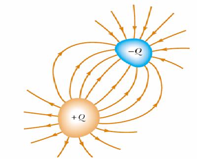
Capacitors: two conductors are charged different signs, but the same
Capacitor circuit

READ MORE - The function of capacitors in electrical or electronic circuits