Selasa, 04 Januari 2011

the first remote control is not damaged


The cause of the first remote control is not damaged, but the sensors in the device (TV / VCD / Compo etc.). The question of how we can determine who damaged remote or device? if any device / remote and another similar maybe we could try it. But when no device or other remote that can be used to try something? quiet .... there are a few tips. Remote control function or not can be tested using the radio AM / MW. Try to turn the radio on a wave MW / AM, then push-push the button on the remote while in the lift to the radio earlier. on the radio when you hear a 'tut' when the push button, means the key / remote control function, means that the damage occurred on the device rather than on remote.Cara second is by pointing the remote at an HP camera, when the remote is in good condition when the button is pressed press there will be light captured by the camera HP

The second reason is the remote battery is discharged, if the test results obtained using a radio remote controller diagnosis is damaged, the first thing to do is, make sure the remote control battery good / not yet finished. Many complaints damaged remote controls just because battery are depleted. For that, prior to the demolition of the remote, it is better replaced with a new battery.


caused because the battery is too long attached and moist or damaged so that the battery terminals cause rusting. When this happens, of course flow from the battery can not supply voltage to the active component remote control, and remote can not stabil. Why most frequent is the use of the cheap batteries that can cause rust usually this type of batteries containing hazardous substances Mercuri.

The fourth cause of dirty or humid PCB board. It can be seen only when the remote control has been dismantled. Things you can do is to perform cleanup of PCB boards from dirt, if there is the dirt trying to clean the PCB with thinner.

The cause is carbon fifth worn thin. Usually remote control, on the button at the bottom (the side in contact with PCB) coated with carbon. if the carbon is exhausted / depleted then the button can not function. If the carbon is exhausted / can be replaced with a thin layer of aluminum voil found on cigarette packs. Or can also be replaced with a new layer of carbon (carbon-coated way with liquid that has been circulating. Carbon this liquid will dry after a few minutes superimposed to the key)

The cause of the six is an infrared LED is damaged. If Led is broken, of data / commands from the remote can not be transmitted to the device which we will control.

The seventh cause of CF components are damaged. This component is a carrier frequency generator data / commands from the remote control. If this component is damaged, of course there will be no data that can be sent to the device that we control. This component is usually a box-shaped legs 2 is also sometimes the legs 3. CF component is usually colored blue / black / yellow / orange.

The cause of the eighth is the remote casing is broken, so we push the button that does not fit on the button on the PCB. This of course will cause the absence of data / commands that we put the remote control.

The cause of the ninth is the path of damaged PCB. This will result in non-functioning remote control. Things you can do is do / grafting or repair track on the PCB.

The cause is damage to the Ten active component on the remote (transistors / IC) when the transistor is damaged just maybe we can replace with similar components and a type that exist in the market. However, if the damaged is the IC, usually can be repaired rmonika

Causes damage to the eleven are passive components (resistors / condensator) damage of this type rarely occur on the remote control.
READ MORE - the first remote control is not damaged

Senin, 30 Agustus 2010

Component-Component Transformer / Transformer / Transformer


Component-Component Transformer / Transformer / Transformer

1. Iron Core
Iron core serves to simplify the way flux, magnetic generated by the electric current through the coil. Made from thin metal plates which insulated to reduce heat (as the iron losses) generated by Eddy Current.

2. Transformer coil
Transformer coil windings are some insulated wire forming a coil or coil. Coil consists of a primary coil and secondary coils are isolated either towards or against the inter-iron core coil with solid insulation such as cardboard, etc. pertinak. The coil as a means of voltage and current transformation.

3. Transformer Oil
Transformer oil is one of the liquid insulating material which is used as insulation and coolant in transformers.
• As part of an insulating material, the oil must have the ability to resist breakdown voltage, whereas
• as transformer oil cooler must be able to reduce heat generated,
so with both the ability of the oil is expected to be able to protect the transformer from the disorder.

Transformer oil has the element or compound contained hydrocarbons are paraffinic hydrocarbon compounds, hydrocarbon compounds and aromatic hydrocarbons naftenik. Besides all these compounds, transformer oils still contain compounds called additive even though its content is very small.

4. Bushing
The relationship between the coil transformers with external network through a bushing that is enclosed by a conductor insulator. Bushing also functions as an insulator / conductor with insulation between the transformer tank. On equipped facilities for testing bushing bushing condition which is often called a center tap.

5. Conservator Tank
Conservator tank serves to hold reserves of oil and steam / air heating due to the transformer due to load current. Between the tank and a transformer which paired relays bucholzt gas will absorb oil production due to damage. To keep the oil is not contaminated with water, tip into the airways through the release channel / venting moisture absorbing media has on the air, often referred to as silica gel and he's not out polluting the surrounding air.

6. Transformer Cooling Equipment Help
In the iron core and coil - the coil will rise due to heat losses from copper. Then the heat resulted in an excessive temperature increase, this will damage the insulation, to reduce the excessive temperature rise transformers need to be equipped with tools or cooling system to channel the heat out of the transformer, the media used in the cooling system can be: Air / Gas, Oil and Water.

In a natural way, streaming media as a result of the temperature difference between the media and to accelerate the cooling of the mainstream media (minyak-udara/gas) by completing a transformer with fins (radiators). If desired distribution of heat more quickly, the manual way can be equipped with equipment to speed up the circulation of cooling media to pump the oil circulation pump, air and water cooling method is called force (Forced).

7. Tap Changer
Quality of electric power operations if its nominal voltage according to the provisions, but at the time of surgery may decrease the voltage so that its quality decreases, it is necessary to stress that the voltage regulator on obtaining the best conditions, constant and continuous.

For the transformer is designed in such a way that changes the voltage on the inlet / input does not result in changes in voltage on the exit / output, in other words, the voltage on the exit / output equipment. This tool is called a voltage regulator leads without termination charges, commonly called the On Load Tap Changer (OLTC). In general, OLTC connected on the primary side and the amount depends on the design and system changes the voltage on the network.

8. Respirator (Dehydrating breather)
As shelter expansion caused by heat insulating oil that may arise, then the oil collected on the tank is often called a conservator. On the surface of the oil conservator is sought must not be in contact with air, because humidity air containing water vapor will contaminate the oil even if the process lasts long enough contamination. To overcome this, the incoming air into a tank of oil to the conservator at the time of cold moisture requires a media vacuum, which is used usually is silica gel. Contrary if a transformer heat so when it shrinks it will suck air from outside into the tank and to avoid contamination by air humidity, we need a media that is used usually sucking moisture is silica gel, which is specifically designed for the purpose mentioned above.

9. Indicators

a. Thermometer / Temperature Gauge, this tool is used to measure the heat from the transformer, both primary and secondary coils heat the oil too trafo. This thermometer works on the basis of mercury (mercury / Hg), which is connected with a tube connected with the expansion and the degree of heat indicator needles.
Some thermometers combined with heat from the resistor (which is connected with the special current transformer, which is inserted in the middle of phase one phase) thus obtained is a relative indication of the heat is actually happening.

b. Surface oil / Level Gauge, this tool serves to high-level appointment of an existing oil in the conservator. There are several types of appointment, such appointment is with immediate estimate on how to install the glass on one side so it will be easy to identify the conservator oil level. While other types if the conservator is designed to complement such a balloon of elastic material and filled with ordinary air and is equipped with protective devices such as the respiratory system so that expansion and contraction of the oil-air balloon into the dry and safe condition.

10. Internal Protection Equipment

a. Bucholzt relays, use of gas detection relay (Bucholtz) in oil immersed transformers is to secure the transformer which is based on disturbances such TRANSFORMER: arcing, partial discharge and over-heating which generally produce gas. These gases are collected in the room will do the relays and alarm contacts.

Gas detection relays also consists of a piece of equipment that responds to the high oil flow abnormalities arising at the time of the transformer serious disruptions. This equipment will move the contact trip that is generally connected with the circuit breakers trip flows from the transformer installation.

There are several types of relays bucholtz mounted on a transformer, Relay type but used to secure space On Load Tap Changer (OLTC) with the same working principle is often referred to as Relay Jansen. There are several types such as relays buhcoltz but there is no gas control, the kind of pressure one uses the membrane / membrane bending tin so that when the pressure changes because they will work disruption, there is no alarm here, but a direct trip and on the same principle only using a safety pressure or pressure switches.

b. Jansen membrane, this means more work for the safety of pressure (Explosive Membrane) / bursting Plate. This works because the relay is more pressure inside the transformer due to interference, because the pressure exceeds the ability of the membrane / membrane attached, then the membrane will rupture and the oil will come out of the transformer oil caused by pressure

c. More pressure relay (Sudden Pressure Relay), a flash over or short circuit resulting in an oil immersed transformers, will generally be associated with a more pressure inside the tank, because the gas formed by decomposition and evaporation of oil. By completing a relay release more pressure on the transformer, then the more pressure that could endanger the transformer tank size is limited. If this pressure can not be eliminated within a few millidetik, then there is more heat to the liquid tank and a transformer to explode. Safety equipment should be quickly worked to evacuate the pressure.

d. Tank safety relays, safety relays work as if there is current flowing in the tank, due to phase disturbance to the tank or the installation of aids such as fan motors, motors circulation and aids the other, heating etc..
This current differential relay as a substitute for a safety relay system is usually mounted on the transformer tank is not equipped with the current transformer primary side and usually on a transformer with a small capacity. Transformer mounted on insulators so that is not connected to the ground and then using a cable which is passed earthing transformer insulation levels and flows with a small ratio and then connected to the relay
ground tank with a current transformer ratio between 300 s / d 500 with the secondary side only 1 Amp.

e. Neutral Grounding Resistance / NGR or Resistance Grounding transformer, is the resistance that is placed between the transformer neutral point to earth, which serves to minimize the disturbance current. Resistance mounted on the transformer neutral point is connected to Y (star / Wye).

NGR normally mounted on a neutral point of 70 kV or 20 kV, whereas at neutral point of transformer 150 kV and 500 kV direct digrounding (solid)

NGR Value:
Voltage of 70 kV = 40 Ohm
Voltage of 20 kV = 12 Ohm, 40 Ohm, 200 Ohm and 500 Ohm

Type Neutral Grounding Resistance
- Resistance Liquid (Water), ie its resistance material is pure water. To obtain the desired resistance value of KOH added salt.

- Resistance Alloy, namely nekelin article is made of metal and made in panels with a pre-determined resistance value.

11. Additional equipment for safety transformers

a. Firefighters, (typically for transformers - large transformer), a modern fire-fighting system at the transformer as it is now very necessary. An important function to prevent or extinguish a transformer fire as quickly as possible transformer in case of fire.

The cause of a transformer fire was due to short circuit the transformer secondary side so that the maximum current will flow. If the process lasts long enough and the relays do not operate. Meanwhile, not as a result of the operation of relays also set the time of opening of the PMT, the relay is damaged, and the DC source that does not exist, as well as damage to wiring systems.

Modern firefighting systems by reducing the oil system automatically so there are spaces where oxygen separator gas forcibly incorporated into the air space that has no oil so no burning oil, and further damage can be avoided, even if the condition becomes damaged transformer .

Oil removal process using gravity or pumps DC motor is a condition that is very risky, because only with an automatic valve controlled by the trigger of the switch due to the heat of the fire and close automatic valves on the valve pipe connecting the oil tank (the conservator) to the transformer (before bucholz relays), and the presence of oxygen gas separator (high-pressure nitrogen gas) is loaded through the pipe to be joined at the bottom of the transformer and then going into the chamber is not filled with oil.

b. Thermometer measuring direct, directly measuring Thermometer is widely used on high voltage installations / sub station, as in the control room, relay room, living room etc. PLC. Room temperature is recorded periodically on the form which has been prepared and evaluated as a material statement.

c. Thermometer measuring indirect, indirect measuring thermometers are widely used on high voltage installations / transformer that serves to determine the change of oil and transformer winding temperature. Oil and transformer winding temperature is recorded periodically / regularly, on a form which has been prepared and evaluated as a report.

12. Transformer Protection Relay and Functions

Type of relay protection in power transformers are as follows:

a. Overcurrent relay (over current relay), serves to secure the transformer against short circuit between phases within and outside the security area transformer. These relays are also expected to have complementary properties with more load relay, this relay also serves as a safety backup on the other installations.

b. Differential relays, relay serves to secure the transformer to short circuit fault happens in the area of safety.

c. Limited ground fault relay (Restricted Earth Fault Relay), the relay serves to secure the transformer to ground the transformer in the security area, particularly near the neutral point of interruption that can not be perceived by the differential relay.

d. Directional overcurrent relays, Directional Over Current Relay, or better known as overcurrent relays that have a certain direction is the Safety Relay working because of the current and voltage quantities that can distinguish the direction of flow disturbances. These relays have two pieces measuring parameters of voltage and current into the relay to distinguish the current direction forward or backward direction of currents, the neutral point earthing transformer using prisoners. These relays installed at 20 KV feeders.

This relay works based on the current source of ZCT (Zero Current Transformer) and source voltage of the PT (Potential Transformers). Source voltage of PT generally use a series of Open-Delta, but did not rule out there that use direct connections three phase. These relays installed on a network of high voltage, medium voltage, also on the safety of power transformers, and serves to secure the electrical equipment due to the disruption of phase-phase or phase to ground. To distinguish the direction of the current one should compare phase with phase voltages on the other.

e. Relay connections, is the angle difference between the current and the input voltage relays at power factor of one. Relay maximum torque angle is the angle difference between the current and the voltage on the relay which produces maximum torque.

f. Ground fault relays, relay serves to secure the transformer if ground fault occurs inside and outside the security area transformer. Direction relay circuit ground signal and operating require polarizing signal. Operating signal obtained from the residual current through the current transformer circuit (IOP = 3Io), while the polarizing signal from the residual stress. Residual stresses can be obtained from the secondary circuit open delta voltage transformer.

g. Ground tank relays, relay serves to secure the transformer against short circuit between the coils of phase with the transformer and the transformer tank is earthed neutral point. Worked as a safety relay in case the current flows from tank to tank due to interference or phase of the installation aids such as fan motors, circulation and auxiliary motors, heaters etc..
The security of this flow as a substitute for the differential relay, safety relay system because the tank is usually installed on a transformer that is not equipped with the current transformer primary side and usually on a transformer with a small capacity. Transformer mounted on insulators so that is not connected to the ground and then by using a grounding wire is passed through a transformer with the current level of insulation and a small ratio, then the tank is connected to the relay current transformer with ratio of soil (CT) between 300 s / d 500 with the secondary side only 1 Amp.

13. Announciator High Voltage Installation System

Announciator are indicators of abnormal events occurred during the installation of high voltage system, both individually and collectively. Announciator coincides with a relay that works because if there is abnormality in the equipment. Annunciator usually in form of written instructions under normal conditions there is no designation, if there is abnormality in the indicator lights are lit in accordance with the conditions of the system at that time. Collection of these indicators are usually referred to as announciator.

Announciator the most complete in the present moment is the installation of SF6 substations, because at the GIS system, a lot that needs to monitor conditions such as gas pressure, humidity of SF6 gas in each compartment, the contact position of PMT, PMS PMS line well, an STD or STD land etc. Rel. For that discussion would be taken from the system annunciator annunciatornya SF6 substations. like. Annunciator at bay (SUTT or SKTT), transformers and Koppel.
READ MORE - Component-Component Transformer / Transformer / Transformer

When Operated Transformer Condition Inspection


Maintenance and Condition Monitoring of Transformer, if his English: "Transformer Condition Monitoring and Maintenance "...( good ...?!! But we must be proud of their own language ... do not ya?). This article is to complement previous articles about the transformer or transformers (up, whichever you use, if I prefer to call it Tr).

By doing regular maintenance and condition monitoring of transformer during operation will be many benefits gained, among others:
• Improving the reliability of transformer.
• Extend the life.
• If the lifetime is longer, it will automatically save the cost of replacing the unit transformer.

The treatment steps of transformers, among other things:
• Periodically check the quality of insulating oil.
• Inspection / Periodic direct observation (Visual Inspection)
• Check carefully-examination (overhauls) are scheduled.

-Main Components Transformer Components

for more details you can read the previous article, "Component-Component transformers", but I show a little of its main components, namely:
• On-load tap changer (OLTC)
• Bushing
• Insulator / insulation
• Gasket
• System filter / oil filter isolation
• Equipment protection;
- Valves or valves
- Relay
- Measuring tools and indicators

When Operated Transformer Condition Inspection

Transformer operating at the time there was some examination and analysis should be done, among others:

1. Examination and analysis of transformer insulating oil, includes:
- Voltage translucent (breakdown voltage)
- Dissolved Gas Analysis (Dissolved gas analysis, DGA)
- Analysis of the overall insulation oil (once every 10 years)

• Examination and analysis of dissolved gas content (Dissolved gas analysis, DGA), to prevent: (partial) discharges, failure of thermal (thermal faults), Deterioration / deterioration of insulating paper / laminate.

• Examination and analysis of the overall insulation oil, includes: power factor (cf. Tan δ), water content (water content), neutralisation number, interfacial tension, analysis and content of furfural negative catalyst (inhibitor content)

2. Direct Observation and Inspection (Visual inspections)
- The physical condition of the transformer as a whole.
- Measuring tools, relays, filter / filters, etc.
- Inspection by using infra-red (infrared monitoring),
every two years.

Actions are usually done at the time of Accurate Inspection (overhaul)

1. Maintenance and inspection light (Minor overhaul), every three or six years.
- On-load tap-Changers
- Oil filtering and vacuum treatment
- Relays and auxiliary devices.

2. Care and thorough examination (Major overhaul)
- Technically, at least one time during its lifetime.
- Cleansing, toning and drying again.

3. Chemical Analysis
- Analysis of insulating paper / laminate (once every 10 years)

4. Electrical Testing (Electrical Test) for equipment;
- Power transformers
- Bushings
- Measuring transformers (transformer measurement)
- Breaker capacitors

Electrical Testing (electrical test) done at least every 6-9 years. Tests performed include;
a. Double measurements
b. PD-measurement
c. Responce Frequency Analysis, FRA
d. voltage tests

Causes of short circuit within the transformer, among others:

• Impaired short circuit between windings for damage to the laminate.
• Changes in gas content of H2, CH4, CO, C2H4 and C2H2
READ MORE - When Operated Transformer Condition Inspection

Selasa, 17 Agustus 2010

The function of capacitors in electrical or electronic circuits

The function of capacitors in electrical or electronic circuits, among others:
a. Storing electrical energy.
b. Avoid stepping on the electric circuit which uses coil, for example, adapter, power supply, and lamps.
c. Selecting a radio wave transmitter which was captured by the aircraft radio recipient (turning)

There are two kinds of capacitors:
a. Non-polar capacitors or negative without the positive pole, low power saving.
b. Bi polar capacitor negative or positive pole, high enough to save power.

Capacitor properties
Can save and clear the electric charge.
Unable to direct current flow.
Current can flow back and forth.
For alternating current of low-frequency.
Capacitors can hamper the flow.

Usefulness capacitor
To avoid stepping on the electric circuit containing a coil when the current is suddenly disconnected.
The circuit used to start the car
To select the wavelength which is captured by a radio receiver.

Capacity (capacitance) capacitor
Capacitance is defined as the ability of a capacitor to hold the charge of electrons to a certain voltage level. With the formula can be written:
Q = CV
Q = charge of electron in C (coulombs)
C = the capacitance in F (farads)
V = large voltage in V (volts)

Parallel chip capacitor is a capacitor consisting of two pieces of conductors separated by dielectric material


The two-chip capacitor is connected to the battery. The battery will provide on-chip charge + q-q in the first and second pieces. In the gap between the two pieces of the electric field will arise.

The capacitance of the capacitor chip parallel computation:
C = ε0 A
d
C = Capacity of the capacitor (F)
ε0 = permittivity of vacuum (8 85x10-12 C2N-1m2)
A = cross-sectional area of each chip (m2)
d = distance between the chip (m)


Capacitors balls are hollow spherical capacitor with a certain radius.

Various kinds of Capacitors Electrolyte Capacitors
1.Condenser electrolyte or electrolytic capacitors (often abbreviated elco) is a capacitor which is usually tubular, bipolar positive has polarity legs (long legs) and negative (short legs).
Consists of two sheets of aluminum foil as a conductor and as a dielectric alumuniumoksida.
2.Fixed Capacitors
Fixed capacitor is a capacitor whose value is constant and unchanging. capacitors remain
three different forms:
Ceramic Capacitors (Ceramic Capacitor) there is a round thin shape, there is a rectangular red, green, brown and other non-polar capacitor lain.Merupakan.
Polyester capacitor
The rectangular shape like candies. Usually has a red, green, brown, and so forth.
Paper capacitor
Composed of two sheets of foil (silver) the length of a conductor which rolled on a cylinder such as a dielectric thin paper inserted. This paper capacitors are often referred to as capacitor padder.

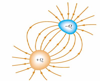
Capacitors: two conductors are charged different signs, but the same
Capacitor circuit

READ MORE - The function of capacitors in electrical or electronic circuits

Jumat, 09 Juli 2010

The working principle Paiton units 7 and 8 in general is a coal burning boiler to heat water and turn water into a very hot steam

BASIC PROCESS Paiton Unit 7 and 8

The working principle Paiton units 7 and 8 in general is a coal burning boiler to heat water and turn water into a very hot steam which is used to drive turbines and generate electricity from the generator coil in the magnetic field. System settings used at the power plant uses a closed loop system settings, where water was used for several rounds of the process is the same water, just need to be added if the existing level of less than point sets. Changing shape, to a certain level of water tangible, but at another level intangible steam.

The process begins with water that is pumped into the condenser, then the condenser is pumped to the polisher to be processed so that the deposition of corrosion and missing, after which it is pumped to the Feed Water Heater 1, 2, 3 and 4 to be heated and then poured into Daerator to eliminate gas - O2 and CO2 and then pumped back into the Feed Water Heater 6, 7, 8 which would then be forwarded to increased temperature in the economizer and then headed to the steam drum to be separated between the steam and water, after which the superheated steam that is going through the First Super Heater, Secondary Super Heater and form a super heated steam that will be used to rotate the HP turbine and the pressure and temperature will drop so the SH steam need reheating which occurs at Re Heater, Re Heater from this SH Steam will be returned to Play the IP and LP turbines. This will occur within the turbine conversion of thermal energy from the steam into mechanical energy that causes the rotor to rotate the turbine to spin. This rotor rotation that will move the generator and finally by the generator mechanical energy is converted into electrical energy.

COAL Handling
Coal is the main fuel Paiton Unit 7 and 8. Coal is used in the form of Adaro coal, Arutmin, Kideco with 1.5% ash content, coal was taken from a coal mine in southern Kalimantan and will continue disuply during the operation. Shipping coal to the plant is done by using two ships with a capacity of approximately 43 000 tonnes, which would then be accommodated in the Coal Pile with a capacity of 670 000 tonnes for use as fuel. Before being used as a fuel, coal will go through several processes, namely Stacking, Reclaiming and Processing. But Coal Handling will only carry out the process of stacking and Reclaming, while for the processing included in the boiler operation and will be discussed in further discussion. Stacking is the process of accumulation of coal from ships. While processing the coal handling system of Shiloh until ready for use in boilers.

Stacking
Stacking is the process of moving coal from ships into the Coal Pile. Some of the other terms in Stacking.

Jetty
Jetty is a dock or berth at the coal-carrying ships Paiton Unit 7 and 8. The depth of this pier is 18 m from the seabed, allowing big ships docked. At Unit 7 and have two of the jetty Jetty Jetty A and B. Each has four fruit Jetty Doc Hopper Car that function to move the coal from the ship to the Belt Conveyor. Doc Hopper Cars position can be altered in accordance with the ship's position, this is controlled by the operator of the Coal Unloading Building Control (CUCB).

Conveyor Belt

Conveyor Belt-shaped kind of large belt made of rubber that move through the Head and Tail Pulley Pulley, both serve to drive the Conveyor Belt and Pulley Tansioning functioning as a conveyor belt. To support its weight belt conveyor fitted coal transported at a certain distance between Idler Pulley Head and Tail Pulley. Idler is a rotating bearing that was passed by the Conveyor Belt. Coal is transported by conveyor poured from a container launcher (Chute) tip of Tail Pulley then moved toward the direction of Head Pulley. Typically, the load of coal will fall into the tub the other launchers, located under the Head Pulley to be forwarded to another conveyor or into storage tanks. Conveyor between each branch with one another are connected with the Transfer House, in addition to the conveyor belt also added a few accessories that aims to increase its flexibility, among others:

  1. Done automatically if the metal detected at the coal sampling stopped.
  2. Metal Detector, Is a tool to detect metals in the mixed coal in the delivery process.
  3. Magnetic Separator, to separate the metals contained in coal in the delivery process.
  4. Belt Scale, to determine the amount of weight tonnase coal transported by belt conveyor.
  5. Dust Supasion serves to:
    - Water Polution controller
    - Spraying ait on coal
    - Saves the coal in order not to dust
    - Preventing the occurrence of sparks caused by heat from the coal dust.

Reclaiming

Reclaming is the process of taking coal from the Coal Pile and distribute it to Shiloh. Some terms in reclaiming among others:
READ MORE - The working principle Paiton units 7 and 8 in general is a coal burning boiler to heat water and turn water into a very hot steam

Modem (modulator-demodulator)


Modem (modulator-demodulator) is a device which is currently the most widely used to connect to the internet, particularly through the phone line. Physically, the modem can be distinguished as an internal modem and external modem. Besides, we know the division based on speed and how it works, whether it be software or hardware modem. There are a few bonus more technical nature, such as error control, data compression protocol Internal and External modems

As shown from its name, an external modem device outside

CPU. external modem connected to the CPU via COM or USB port. modem of this type typically use a separate voltage source adapter. The advantage of this type of modem usage is a good enough portability easily removable for use on other computers. Besides using an external modem, there should be no expansion slots that were sacrificed so that it can be used for other purposes, especially if the mainboard is used only to provide a bit expansion slot. external modem is also equipped with an indicator light that enables us to monitor modem status. The disadvantage is more expensive than internal modems. external modems also require a separate place to put it even smaller.

Unlike an external modem, internal modem installed directly inside the CPU. Physically, the form of an internal modem card plugged into one of the expansion slot on the mainboard, usually on the ISA or PCI slot. Use of this type of modem has several advantages, among other places and is more efficient in terms of price is more economical than an external modem. Because they have been installed in the CPU, the modem type does not require an adapter as an external modem so impressed with the system more compact without a lot of milling about the cable that could give the impression of less tidy. However, the internal modem has a weakness as the absence of indicators that can be found on external modems. As a result somewhat difficult to monitor the status of the modem (though it can be done via software). In addition, the internal modem is not using their own voltage source to be supplied from the power supply to the CPU. Heat from the components in a series of internal modems will also increase the temperature within the CPU box.

Modem Speed

The speed of a modem is measured in units bps (bits per second) or kbps (kilobits per second). The amount varies between 300 bps to 56.6 kbps, but the speed commonly used today ranges from 14.4 to 56.6 kbps. The higher the speed the better course because it will shorten the connection time and save on telephone costs. The connection speed is also very dependent on the quality of phone lines used. 56.6 kbps modem is usually very rarely reach top speed. Generally, the fastest connection that can be achieved through conventional phone lines are ranging from 45-50 kbps for downstream, depending on the distance from the central telephone lines are used (of course the closer the better), whereas for the upstream maximum of only 33.6 kbps. This deals with the limitations of phone lines that are basically not designed for high speed data communications.

Hardware and Software-based modems

In addition to the second division of the above, we also know the terms of hardware or software modem. modem that works in hardware using a special chip to handle data communications functions, while on a software modem, this job was taken over by a driver program. Using software modems will be enough CPU work load, and thus would require a system with a fast processor (Pentium processor recommended minimum using 200 Mhz). Loss in performance will be felt when using this type of modem. A Celeron 400-based machines, for example, is only able to work like a PC Pentium Classic while online by using a software modem. Physically there is almost no striking features that distinguish between these two types of modems. However, nowadays almost all PCI-based internal modems on the market is a software modem. These types of modems are generally sold at a price much cheaper than hardware-based modems. Because of the availability factor of the driver, then the software modems are generally only works in Windows OS environment so that the type of modem is also often referred to as Winmodems.

Meaning of indicator light on external modems

OH: Off Hook
Indicates that the modem was working. If likened to a telephone, OH will light up when the receiver was appointed and die when the receiver is placed.

CD: Carrier Detect
Indicates whether there are carriers that are sent from the modem to be contacted or not. When there is a connection with another modem, CD lamp is lit.

AA: Auto Answer
Modem facility that can automatically answer the call from another modem. If the AA indicator lights up, the modem can perform handshaking automatically.

EC: Error Control
Modem facilities for error correction. EC indicators are illuminated to show the modem error correction facility is active.

TD: Transmit Data
The indicator will light when the modem is sending data.

RD: Receive Data
The indicator will light when the modem receives the data.

DTR: Data Terminal Ready
The indicator shows the modem is ready for use to connect to another modem
READ MORE - Modem (modulator-demodulator)

Rabu, 17 Februari 2010

electron gun


An electron gun (also called electron emitter) is an electrical component that produces an electron beam that has a precise kinetic energy and is most often used in televisions and monitors which use cathode ray tube technology, as well as in other instruments, such as electron microscopes and particle accelerators. Electron guns may be classified in several ways:

* by the type of electric field generation (DC or RF),
* by emission mechanism (thermionic, photocathode, cold emission, plasma source),
* by focusing (pure electrostatic or with magnetic fields), or
* by the number of electrodes.

Cathode rays (also called an electron beam or e-beam) are streams of electrons observed in vacuum tubes, i.e. evacuated glass tubes that are equipped with at least two metal electrodes to which a voltage is applied, a cathode or negative electrode and an anode or positive electrode. Electrons were first discovered as the constituents of cathode rays. In 1897 British physicist J. J. Thomson showed the rays were composed of a previously unknown negatively charged particle, which was later named the electron. Cathode ray tubes (CRTs) create the image in a classic television set.

The electron is a subatomic particle carrying a negative electric charge. It has no known components or substructure, and therefore is believed to be an elementary particle.

A particle accelerator is a device that uses electromagnetic fields to propel charged particles to high speeds and to contain them in well-defined beams. An ordinary CRT television set is a simple form of accelerator. There are two basic types: electrostatic and oscillating field.

In the early 20th century, cyclotrons were commonly referred to as atom smashers.
An electron microscope is a type of microscope that produces an electronically-magnified image of a specimen for detailed observation. The electron microscope (EM) uses a particle beam of electrons to illuminate the specimen and create a magnified image of it. The microscope has a greater resolving power than a light-powered optical microscope, because it uses electrons that have wavelengths about 100,000 times shorter than visible light (photons), and can achieve magnifications of up to 1,000,000x, whereas light microscopes are limited to 2000x magnification.

The electron microscope uses electrostatic and electromagnetic "lenses" to control the electron beam and focus it to form an image. These lenses are analogous to, but different from the glass lenses of an optical microscope that form a magnified image by focusing light on or through the specimen.

Electron microscopes are used to observe a wide range of biological and inorganic specimens including microorganisms, cells, large molecules, biopsy samples, metals, and crystals. Industrially, the electron microscope is primarily used for quality control and failure analysis in semiconductor device fabrication.

In the view above, one can see the electron gun. The piece of waveguide feeding the gun has a window that seperates the high vacuum side from the rest of the waveguide that is presurized with Sulfur Hexaflouride. electron gun to shoot at each particle position phosfor on a shadow mask, shadow mask is a layer that filters out files that mistakes can be shot from dihindarkan.Berbagai color distortion can be generated by varying the intensity of each beam of electrons.


After leaving the Electron Gun, the electron beam travels through the Alpha Magnet which selects electrons with similar energies. One is able to see both the electron gun as well as the beginning of the Linac in this photo.


READ MORE - electron gun