Rabu, 21 November 2012

Sawtooth wave oscillator


Sawtooth wave oscillator

The figure on the left shows the case that the A point is positive voltage.
When the A point is positive voltage, the electric current flows to the capacitor(C) through D1 and R1. When the value of R2 is small compared with R1, the B point falls to the negative voltage at short time.

The A point changes into the negative voltage rapidly when the B point falls to the negative voltage and the positive input terminal of IC1 falls below a few 0 V.
For the positive input terminal of IC1 to fall below 0 V, the condition of R3>R4 is necessary.


The figure on the left shows the case that the A point is negative voltage.
When the A point is negative voltage, the electric current flows from the capacitor(C) through D2 and R2. When R2 is big compared with R1, the B point becomes the positive voltage, doing comparative slow.

The A point changes into the positive voltage rapidly when the B point rises to the positive voltage and the positive input terminal of IC1 exceeds a few 0 V.
For the positive input terminal of IC1 to exceed 0 V, the condition of R3>R4 is necessary.

READ MORE - Sawtooth wave oscillator

wave oscillator


In this page, I introduce the sawtooth wave oscillator which used the operational amplifier (TL082).
The composition of this circuit is the same as the triangular wave oscillator basically and is using two operational amplifiers. At the circuit diagram above, IC(1/2) is the Schmitt circuit and IC(2/2) is the integration circuit.
The difference with the triangular wave oscillator is to be changing the time of the charging and the discharging of the capacitor. When the output of IC(1/2) is positive voltage, it charges rapidly by the small resistance(R1) value.(When the integration output voltage falls) When the output of IC(1/2) is negative voltage, it is made to charge gradually at the big resistance(R2) value. The output waveform of the integration circuit becomes a form like the tooth of the saw.
Such voltage is used for the control of the electron beam (the scanning line) of the television, too.
When picturing a picture at the cathode-ray tube, an electron beam is moved comparative slow.(When the electron beam moves from the left to the right on the screen)
When turning back, it is rapidly moved.(When moving from the right to the left)

Like the triangular wave oscillator, the line voltage needs both of the positive power supply and the negative power supply. Also, to work in the oscillation, the condition of R3>R4 is necessary. However, when making the value of R4 small compared with R3, the output voltage becomes small. The near value is good for R3 and R4. You may make opposite if not oscillating using the resistor with the same value. The circuit diagram above is using the resistor with the value which is different to make oscillate surely.


When calculating at the value which is shown with the circuit diagram,
the oscillation frequency is as follows.
f = (1/2C(R1+R2))x(R3/R4)

 = (1/(2x0.1x10-6x(5.6x103+100x103))x(120x103/100x103)

 = (1/(21.12x10-3))x1.2

 = 56.8 Hz

READ MORE - wave oscillator

Large Scale Integration


Levels of Integration

ICs are categorized according to their circuit complexity which can be measured by the number of electronic components contained in the package. The process of integration can be classified as small, medium, large, very large, or super large.

Small-Scale Integration (SSI) – SSI devices contain several independent electronic components in a single package. The inputs and outputs are connected directly to the pins in the package. The number of components is less than 10 in every package. Logic Gates like inverters, AND gate, OR gate and etc. are products of SSI.

Medium Scale Integration (MSI) – MSI devices has a complexity of 10 to 100 electronic components in a single package. They usually perform basic and specific digital operations and includes decoders, adders, counters, multiplexers, and demultiplexers.

Large Scale Integration (LSI) – Products of LSI contain between 100 and 10,000 electronic components in a single package. They include memory modules, I/O controllers, and 4-bit microprocessor systems.

Very Large Scale Integration (VLSI) – Devices that are results of VLSI contain between 10,000 and 300,000 electronic components. VLSI produces large memory modules and 8bit, 16-bit, and 32-bit microprocessor systems.

Super Large Scale Integration (SLSI) – This kind is a new type of integration which produces ICs having more than 300,000 electronic components in one package. Examples of devices which use SLSI are 64-bit microprocessor systems and microcontrollers.


Common Kinds of Integrated Circuits

Voltage Regulator – A voltage regulator IC is a three-terminal linear IC which is capable of providing extremely stable voltage supply. Many different voltage regulator ICs that can supply load currents from 100mA to 3A are available commercially. This type of ICs commonly has a feature called thermal shutdown. When the internal temperature of the IC reaches a certain temperature (typically +175 deg. Celsius), the regulator shuts down and prevents the chip from getting any hotter. This protects the IC from excessively high value of heat which may destroy it and damage the connected circuit or load. The LM340 series is a popular series of voltage regulator ICs. They provide regulated voltages of 5, 6, 8, 10, 12, 15, 18, and 24V. Common applications of voltage regulator ICs include power supplies.

Operational Amplifier (OP Amp) – OP Amps are the most commonly used type of linear IC. It is a type of amplifier with a high gain, which means that the ratio of the output to input voltage is in high percentage. Aside from being amplifiers, OP Amps can also be used as voltage comparators.

Logic IC – This type of integrated circuit is the commonly used of all digital ICs. These ICs contain gates which correspond to the logic functions of AND, OR, NAND, NOR, XOR, XNOR, and NOT. Other types of digital ICs are created by creating different combinations of these logic gates.

Multiplexer – A multiplexer is a type of digital IC which contains combinational circuit that selects binary information from one of many inputs and directs it to a single output line (many to one). Multiplexer ICs have select pins that determine which of the many inputs should be selected as the output.

Demultiplexer – Demultiplexer IC is the counterpart of multiplexer IC. It accepts one input and directs the input to many output lines (one to many).

Decoder – Decoder ICs are kinds of digital ICs that are capable of converting binary information to a format which is understandable by humans. For example, the binary digit 0101 can be decoded by a decoder IC and be displayed as a numeric number 5 in a 7-segment display component.

Adder/Subtractor – These are digital ICs that perform the basic operation of binary addition and subtraction. There are no ICs which can perform multiplication and division operations but these mathematical functions can be performed by using Adder and Subtractor ICs along with other ICs like counters.

Flip-flop – Flip-flops are the basic elements of a sequential logic circuit. They are digital devices which produces outputs in reaction to a series of inputs. Unlike logic gates, they do not have predetermined output values because their output depends on the sequence of inputs. Flip-flops are contained in different IC packages.

Counter – Counters are created through the combination of different flip-flops. Counters produces a string of outputs which follows a specific pattern. For example, the output of a counter IC may be from 0000 to 1111 (that is a count from 0 to 15).

Registers – Registers serves a storage of bits of information. They are often associated with clocks and mainly composed of flip-flops. Register ICs come in different packages which have different storage capacities.

Clocks/Timers – These are ICs which are capable of producing signals which could serve as inputs to other ICs or gates. Clock signals are commonly used to synchronize the operations of a sequential circuit.

READ MORE - Large Scale Integration

LM386


This is the low frequency power amplifier of which the penumbra article can be composed without using it hardly.
The about 660-mW output can be gotten with the 16-ohm speaker.


This circuit is used for the simple monitor and so on.
The impedance (4-ohm and 8-ohm, and so on), the output power of the speaker and so on are specified by the standard but are OK rather than strict. Because the sound cracks (warping) when presenting the output above the rating, it uses naturally within the standard.
When conscious of the timbre and the output power, it is better not to do the use of this circuit.

The use example : TV sound monitor circuit of Frequency divider and so on.

--------------------------------------------------------------------------------

Data for LM386

Operating voltage range : 4 to 12V(LM386NN)
5 to 18V(LM386N-4)
Current in the standing still : 4mA(typ)
Package : 8 pins
Plastic DIL(code N)

The maximun rating (Ta=25°C)
Vs : 15V(LM386N)  Tstg : -65 to +150°C


 22V(LM386N-4)
 Tj : 150°C
PD* : 660mW(LM386N)
 Rth(j-a) : 187°C/W(LM386N)


 1.25W(LM386N-4)


 100°C/W(LM386n-4)
VIN : ±0.4V
 Tpin : 300°C.10sec
Topt : 0 to +70°C
 * : Ta = 25°C


READ MORE - LM386

voltage


This circuit is used when delaying the standing-up of the square wave signal.
Also, in the case having to do with the pulse of the input signal, it uses for the circuit as it changes the output voltage gradually by the occurrence frequency of the pulse, too. In the case, the resistor must be put in parallel with the capacitor to miss the electric charge which was stored up at the capacitor.

The use example : Door lock signal making circuit and voltage change circuit of Car speed detection device and so on.

The photograph above is the one of the following condition.
F : 50Hz
R : 10K-ohm
C : 0.22µF

The electric charge begins to store up in capacitor(C) when the voltage is applied to the input. The electric current which flows into capacitor as the electric charge is stored up decreases.
The electric current change which flows through the capacitor(C) and the resistor (R) is demanded by the following formula.

i = (V/R)e-(t/CR)

i : The electric current which changes in the time(A)
V : The applied voltage(V)
R : The resistance value(ohm)
C : The capacitor value(F)
e : The base of the natural logarithm(2.71828)
t : The elapsed time after the charging beginning(sec)
CR : The capacitive time constant (C x R)


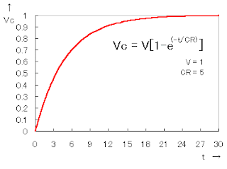
The change of the voltage(Vc) which appears in the both edges of the capacitor(C) becomes the following formula.

Vc = V[1-e-(t/CR)]

It is as follows when showing the formula above by the graph.


READ MORE - voltage

Voltage change circuit


This circuit is used when getting the signal having to do with the pulse from the input signal of the square wave.


The circuit of this form is used to interrupt the relation having to do with the direct current among the circuits, too.(Direct current cut) In the case, the signal of the square wave causes the warp. Also, in case of the analog signal, the voltage which is output in the capacity of the capacitor changes. The influence comes out to the extent that the input signal is low-frequency.

The use example : Voltage change circuit of Car speed detection device and so on.

The photograph above is the one of the following condition.
F : 50Hz
C : 0.22µF
R : 10K-ohm


to the input. The electric current which flows into the capacitor as the electric charge is stored up decreases.
The electric current change which flows through the capacitor(C) and the resistor (R) is demanded by the following formula.

i = (V/R)e-(t/CR)

i : The electric current which changes in the time(A)
V : The applied voltage(V)
R : The resistance value(ohm)
C : The capacitor value(F)
e : The base of the natural logarithm(2.71828)
t : The elapsed time after the charging beginning(sec)
CR : The capacitive time constant (C x R)


The change of the voltage which appears in the both edges of the resistor (R) becomes the following formula.

iR = V[e-(t/CR)]

It is as follows when showing the formula above by the graph.


READ MORE - Voltage change circuit

Tunnel Diode


A diode is an electronic device having two electrodes; one of which is positive (called the anode) and the other is negative (called the cathode). The node at which these two electrodes meet is called the P-N Junction. Because of having only a single P-N junction, the diode serves as a one-way conductor that allows current to flow only in one direction.

Current flows through a diode only when the diode is in the forward-bias or ON state. This happens when a positive voltage is applied to the anode and the negative voltage is applied to the cathode. During this state, the internal resistance of the diode is very small, that is why current can easily pass through it. On the other hand, when a voltage is applied across the diode such that the anode is connected to the negative voltage and the cathode is receiving the positive voltage, the diode is said to be in reverse-bias OFF state. While in the reverse-bias state, the diode has a very high internal resistance making it impossible for current to pass through it.

The process of allowing current to flow only in one direction is called rectification. One of the most common applications of the diode is rectification. It is often used to convert alternating current to direct current. However, there are different special-purpose diodes which perform more than rectification.


Special-Purpose Diodes

Capacitive or Varactor Diode – Also called varicap, this diode, when operated in reverse-bias, serves as capacitance. The capacitance value is in picofarad. This capacitance can be controlled by varying the reversed input voltage.

Zener Diode – The zener diode is a voltage reference diode. They are used to maintain a fixed amount of voltage. Zener diodes are designed to have a specific reverse “breakdown” voltage. The breakdown voltage is the voltage that the diode can keep constant while operating in reverse-bias. This type of diode is widely used for voltage regulation in dc power supplies.

Tunnel Diode – Also called Esaki Diodes. The important feature of this type of diode is its negative resistance while operating on a certain range of forward voltage. With this characteristic, the diode allows an increase in current when the voltage is decreased. Because of this, the tunnel diode can be used as an amplifier.

Light-Emitting Diode (LED) - The LED is a special-purpose diode that can produce light as current passes through it. Because of this characteristic, the LED is widely used as a basic display component, especially that it requires less power to operate compare to other display units. The typical voltage value needed is 1.6 V to produce 20mA of current. LED’s come in different colors like red, green, blue, yellow, and orange. There are also multi-colored LED’s and blinking LED’s.

Photodiode – This type of diode is made up of photosensitive materials such as sulfide and cadmium, where the resistance decreases with more light. The resistance value without light is called the dark resistance and is typically in the range of megaohms. Being sensitive to light, the photodiode is usually used for many light-control devices.

READ MORE - Tunnel Diode

Senin, 19 November 2012

Power amplifiers

Amplifier power circuit from the beginning until now not much changed. Some say this is good circuit, the circuit is good but fitting assembled and tested the result was not as we expected. The problem there is usually treble is less smooth, less noise fast, broken voice, buzzing, tested middle ground bass sound is lost. so you do not have to believe what people say 100%. Quality amplifier built-up certainly different from the amplifier assembly, the circuit will be the same but the quality depends on who assemble. Want to know the secret? Here are a few tricks to try. COPING hum: Power amplifiers are often used in the field blazer. The series is said to said the bell was assembled. But you do not immediately attracted to this power, the circuit is rather complicated and difficult to understand intelligence reflects the person who first desain. I think a great power is the power of simple, inexpensive, easily assembled and rational. We do not need to use the component with high prices such as tantalum capacitors, power MOSFET and other expensive. This does not determine the quality of the power amp once we raft. Great power sometimes cause hum, to overcome that is to separate the signal ground (ground socket, chassis ground) and ground power. SETTINGS TO CIRCUIT IDLE trimpot: Turn the trimpot the current (if any) until the drain current of 50-100mA on each power transistor, in order to avoid defects treble volume positioned above at 10. The risk heatsink so hot! (This marks the setting klass A-AB) SETTING OFFSET trimpot DC: At the time no signal input, turn the trimpot offset so that the voltage at the speaker actually read 0 volts. If you do not want to bother, use and trust only circuit with ic HA17741 type of Hitachi or other qualified IC brand! This is the heart of the series, 90-95% of the quality of the circuit is determined from IC!!! OVERCOMING THE VOICE sluggish / LESS fast: Use the pre-amp circuit to increase the signal of at least 2 times. normally and should pre-amp circuit using IC op-amp with +12 V minimum supply-12V. Raise his mid tone! you do not want to just use the tone control circuit IC that is mid-him! The secret is not in his mid-tones alone but the signal output from IC op-amp is usually great. TREBLE SPLITS: Excessive treble will damage the power amp, power instead of going out even exhausted. Sort it out, attach the filter capacitor 1nF to the power amp input to ground to ensure that the signal is not disabled. Always use a quality active components such as ICs and transistors, the price difference will also be 500 different results. Use a large and short as possible, especially for foot power transistors, and the transistors should be directly soldered to the PCB. CAPACITOR SUPPLY ... Usually power for field use supplay transformer 50V CT 50V, 42V or at least 42V ct. The greater the supply voltage is greater wattage channeled though written in a series of just 300-400 Watt. This course uses elko capacitor-voltage 80-100V. 10.000uF/100V capacitor will be equal to 4X10.000uF/50V. Try to use a strong elko temperature 105 'C. Capacitors are strong in supply of more than nominal voltage written on the body, usually exceeded by 25%. For example, the capacitor will equal 4700uF/50V 4700uF/63V 105'C 85'C. So that was not fast elko explode if given full voltage, keep the temperature as cold as possible. BASS LOST IN THE FIELD: Try using a driver speakers that have a large spool diameter fitted with a suitable sized bok. Usually included examples of parameters and reference dimensions bok, but given the reference box is not always as expected, not only on the ACR, Kicker Subwoofer do too. Size is usually larger than bok-bok bok2 sold in the market. If you force use bok from the market, use driver type G12-80 (sorry no fear campaign called brand) speakers with bass tones for a size small bok. Bok wall should be thick, strong and do not forget glued!!! Bok will not be glued to a different sound, especially the bass tones, prove it!!! See also Power OCL modif to speaker 15 "& 18" SENSOR HEAT Form of transistor, the transistor is usually type BD139 MJE340 or it could be lying there in the middle, flanked by a pair of transistors that newfangled same. These transistors should be mounted on the main heatsink to detect the heat generated by the power transistor. It acts to reduce the bias current at the time of the hot heatsink. So what power transistor heatsink and heat must be set in position? Yes objectives nothing to prevent the signal from the defect (in class A or AB), the consequences of heat. This class is not necessary and will not be felt if you just want a bass tones only. Goal setting on. AB grade is still crystal clear sound even though the volume of the maximum rotated position (center field). It does not seem possible, but this is closer. BIG heatsink Not only is it easier electrolytic capacitors explode in high temperatures, power transistors can also break away under stress break the original. For example 2SC5200 transistor has a voltage of 230Vdc break, but if temperature break higher then its rated voltage will drop well below this value, resulting in fast transistor is damaged. Use of heatsink and cooling fan is very important not only to reduce the heat, more than it can prevent the transistor from break / damaged and weakened output. The more heat the temperature will be less ability. The use of cooling is expected that the components remain fresh, fit and durability. COMPONENT SELECTION: TRANSISTOR POWER There are so many makes and models of these transistors, for example MJ15003 & MJ15024-4-5 from Motorola, but unfortunately these components are not manufactured by Motorola again but from ON Semiconductor. Just different brands can reduce the quality and customer trust. Transistor models jengkol usually stronger at high temperatures, probably because it is more airtight. According to some friends, the character of the transistor jengkol the middle is more powerful, especially when it's hot. 2SC5200 from Toshiba, this transistor innards equal to Sanken 2SC2922, and both will break if the temperature is too hot. Sanken 2SC2922 issued tin granules when heated, these weaknesses. 2SC3281, transistor is the most popular, most linear in the cold-warm temperatures and is often used in professional amplifier, but Toshiba is no longer produced, instead ya C5200. If transistor C3281 is still on the market, then it most likely is fake!!! Sanken 2SC2922 most recognized characters padded. Toshiba 2sC5200 low and also most preferred because it is considered the most linear character and suitable to the taste of ear audio DIYer. TRANSFORMER There are two models of transformers are often used, namely EI models (box / conventional) and model Toroid (Ring / donuts). Some say toroid transformer models better because it has a smaller fluk leakage, in fact the same, or maybe bigger toroid radiation. Circuits are sensitive to this flux is high have a gain circuit as a pre-amp and pre-amp head mic. The circuit is usually installed horizontally / flat parallel with conventional transformer email wire arrangement so that the circuit receives a larger drone. Unlike the toroid transformer models are arranged in a vertical wire email so the wires are perpendicular to kits circuit. The effect is the received fluk kit pre-amp head smaller. To overcome this fluk that does not go into the circuit is to download shelding / fortify a solid aluminum plate oxygen impermeable. Plat is of course connected to the ground via a cable. To match the vertical transmission fluk, conventional transformer needs in pairs oblique (side by side be side down) so that the composition of the transformer wire standing, this way is often used in built-up POWER2. It makes us have to choose a high casing. Voltage 50V 50V CT can be obtained by combining the two transformers 25VCT25V, CT is not used, the foot so the foot 50V 25V used only to CT, so the total number is 100V or 50VCT50V. It is worthy to pwr amp power over 400Watt. RESISTOR 5W Resistors on the legs of the power transistor is usually worth 0.5 ohm 5 Watt white boxy. If we dismantle innards it appears there was a circular aluminum wires. It resembles the inductor, the inductor inductive reactance will be high when fed a high-frequency signal that treble tone will be weakened and deformed. But often it is expected to weaken the treble disability. Power required to issue high-pitched (treble) is certainly larger, there is a problem here. Using R 0.5/5W the power amplifier home its only. But often unrecognized cause of damage to the speakers and power amplifiers is the high treble tones. Treble is not out but was hit by a pwr amp so that arises is hot and damaged. We recommend using common 2 Watt resistor 00:47 - 1 ohm parallel 2 as starting 4 Watt. Or if you use ohm 2 Watt resistor 0:22 parallel unnecessary because sufficient voltage clamp half (one R 0.5/5W replaced the R 0.22/2W) its ok. FUSE Properties of semiconductor material damage / transistor power amplifier is short, if you use a high enough supply then the destruction of the transistor will invite partners to broken anyway. In order for the destruction of transistor is no need for installation of fuses congregation. 1.5A per power transistor is enough.
READ MORE - Power amplifiers

Subwoofer


Simple and low cost. The optimal accumulation voltage is about 50V, but this amp assignment from 30 to 60V. The acute ascribe voltage is about 0.8 – 1V. As you can see, in this architecture the apparatus accept a big tolerance, so you can body it about of the components, which you acquisition at home. The and transistors can be any NPN blazon ability transistor, but do not use Darlington types… The achievement ability is about 60W.
Descriptions:
- capacitor C1 regulates the low frequencies (bass), as the capacitance grows, the low frequncies are accepting louder.
- capacitor C2 regulates the college frequencies (treble), as the capacitance grows, the college frequencies are accepting quiter.
- this is a chic B amplifier, this means, that a accepted charge breeze through the end transistors, alike if there is no arresting on the input. This accepted can be adapted with the 500Ω trimmer resistor. As this accepted incrases, the complete of the amplifier gets better, but the end transistors are added heating. But if this accepted decrases, the transistors are not heating so much, but the complete gets worse…
Related Posts
300W Subwoofer Power Amplifier Wiring Diagram
300W Subwoofer Power Amplifier Wiring Diagram Please agenda that the blueprint for this amp has been upgraded, and it is now recommended for connected aerial ...
150W Car Power Amplifier Circuit
150W Car Power Amplifier Circuit When the amplifier is installed abaft in the suitcase, we shall charge a about-face works stop. The LA47536 possesses a ...
LM317T Solar Battery Charger Circuit
A baby solar console makes an accomplished array charger for AA and AAA rechargeable batteries. Only a few apparatus are appropriate and architecture is actual ...
NiCad Battery Charger Circuit and Schematic
This array charger ambit is advised for recharging NiCad batteries based on an AC-powered accepted antecedent method. It can crank out as abundant as 1 ...
13.8V 20A Transformerless Power Supply Circuit
READ MORE - Subwoofer

Minggu, 04 November 2012

A63 voice recording


Looking to add a custom sound, melody, or message to your next project?  The A63 voice recording module offers true single chip solid state storage capability and requires no software or micro-controller support. It provides high quality recording and playback up to 20 seconds.  One modification allows up to 30 seconds.

Specifications:

L: 1-1/4" W: 1" H: 5/8"
Requires 5-6 VDC power supply
(Need a Power Supply?)
Non volatile flash memory technology
No battery back up required
2-keys operation, record and play back
Low power consumption
LED to indicate recording
Built-in condenser mic
Automatic power down
Requires speaker for playback - low output unless amplifier is use
READ MORE - A63 voice recording

STK4432


This complete high quality, low noise stereo audio power amplifier is based around the Hybrid Integrated Circuit STK4432 manufactured by Sanyo. The circuit incorporates volume and balance controls and has a maximum music output power of 55W per channel (35W per channel RMS). The circuit incorporates an on board power supply; therefore, only an appropriate transformer is required to power the circuit.

Specifications:

Supply voltage: 30 to 36V AC transformer / 2 to 3A
or 30 to 36 VDC at 3 Amps - NOT INCLUDED
Input sensitivity: 300mV
Output power using 36V AC:
Music power – 2 x 55W / 4 Ohm
RMS power – 2 x 35W / 4 Ohm
Includes volume and balance controls
Maximum distortion: < 0.2%
Frequency response: 30Hz to 30KHz
PC board dimensions: 4-3/4"L x 2-1/8"W x 2-3/4"H

READ MORE - STK4432

TDA2003


This is a compact, yet powerful audio amplifier using two TDA2003 monolithic Integrated Circuits connected in bridged configuration to achieve more output power at 12V DC supply. It can deliver more than 20W of music power into a 4-Ohm speaker and is ideal for any kind of audio amplification application.

Specifications:

Supply voltage: 12 to 18V DC / 2A
Based on two TDA2003 Integrated Circuits
Input sensitivity: 100mV / 47K Ohm
Output power using 18V DC supply:
     Music power: > 22W / 4 Ohm
     RMS power: 16W / 4 Ohm or 12W / 8 Ohm
Frequency response: 30Hz to 20KHz (-3dB)
Includes two gold-anodized heat sinks
Includes volume control

READ MORE - TDA2003

HA 13001 IC


A high quality electronic audio amp that can operate on a low voltage, 12 VDC recommended. Uses the Hitachi HA 13001 IC and a dozen external components for a compact and powerful monaural amplifier. Will drive two 4 or 8 ohm speakers. Two can be used for stereo.

Specifications:

L: 2-1/4" W: 1" H: 1-1/2"
Requires external 12 VDC Power Supply
(Need a Power Supply?)
Output up to 18 watts

READ MORE - HA 13001 IC

TDA2009A


This class AB stereo audio power amplifier is designed for quality hi-fi applications using a TDA2009A module. It is easy to construct and has a minimum of external components. The module has output current and thermal protection. This is the data book circuit which outputs excellent sound. The supply voltage for this kit is 8 - 24V DC at 1 to 2 Amps.  Maximum output power will only be obtained with a power supply of at least 20V and greater than 1.5 A, and using 4 ohm speakers.  Powerful enough to power a stereo for a mid-sized room and more than enough for use in an automobile.

Specifications:

L: 3" W: 1-3/4" H: 1-1/2"
Requires external 8-24 VDC Power Supply
(Need a Power Supply?)
Output up to 10 watts per channel

READ MORE - TDA2009A

TBA810 Integrated Circuit


This amplifier circuit is a compact design AF amplifier based on the TBA810 Integrated Circuit. Its low consumption and compact dimensions make it ideal for all kinds of audio amplification applications. The circuit incorporates an overload protection circuit and volume control. In addition, the circuit has low/high impedance inputs which can be connected to any audio source.

Specifications:

Supply voltage: 12 to 16V DC / 0.5A - (Need a Power Supply?)
Based on the TBA810 Integrated Circuit
Input sensitivity: 100mV / 47K Ohm
Output power: 7W Max. / 4 Ohm
Frequency response: 40Hz to 18KHz (-3dB)
Includes volume control
PC board dimensions: 1.75" x 2.25"

READ MORE - TBA810 Integrated Circuit

stereo amplifier module


This is a 1 watt per channel, stereo amplifier module Kit using two LM386N IC’s from National Semiconductor. It is basically two of our CK700’s on a single PC board, with a dual gang pot. It will operate best from 6-12V DC and will work well from a battery since the quiescent current drain is only 10 mA. It requires no heat sinks for
normal use. The input and output are both ground referenced. Maximum output will be obtained with a 12V power supply and 8 ohm speaker, however it is particularly suitable for driving headphones from a supply as low as 4V.

Specifications:

L: 2-1/2" W: 1-3/8" H: 1"
Requires external 4-12 volt dc
(Need a Power Supply?)
Power output : > 1 Watt max. @ 8 ohms, 12V DC ~ 0.4 Watt RMS cont. per channel

READ MORE - stereo amplifier module

Stereo Amplifier Kit


6-10 Watt Stereo Amplifier Kit
Kit 143 is a class AB stereo audio power amplifier designed for quality hi-fi applications using a TDA2005 module. It is easy to construct and has a minimum of external components. The module has output current protection and thermal protection. This is the data book circuit which produces an excellent sound. The supply voltage required for this kit is 8 - 18V DC at 1 to 2 Amps. Maximum output power will only be obtained with a power supply of at least 2A at 15V DC, and using 2 ohm speakers (or 2 by 4 ohm speakers in parallel). However approximately 4W per channel can be obtained with only a 15V DC, 1A supply into 4 ohm loads. The power supply should be well filtered to reduce mains hum, the on board capacitors alone are not adequate for this purpose but are necessary to ensure stability. Extra filtering is unnecessary if operating from a battery.

We spent a lot of time getting the tracks right on this single sided PCB to get the lowest possible THD. Getting the separate tracks to the earth pin is the secret.

Specifications:

L: 3" W: 1-7/8" H: 1"
Requires external 8-18 volt DC @ 2 Amps for Max Output
(Need a Power Supply?)
Frequency response : ~ 15 Hz to 50 kHz, –3 dB

READ MORE - Stereo Amplifier Kit

amplifier designed


This Electronic Kit is an amplifier designed with portability in mind; ideal for battery applications. A full watt from each channel, excellent fidelity. Uses a Samsung KA2209 IC. Small size, circuit board is 1-3/8" x 2". All basic parts supplied, including PC board; you supply two 8 ohm speakers. We suggest a six volt or nine volt battery pack using AA cells; Use D cells if extra long battery life is required. Amplify your CD or Walkman etc - DIY Kit 8.

Specifications:

L: 1-3/8" W: 2" H: 3/4"
Requires external 6-9 volt dc
(Need a Power Supply?)
Output up to 1 watt per channel

READ MORE - amplifier designed

Stereo Preamplifier


This Stereo Preamplifier (Kit 100) is based on the TDA1524A IC.  It contains all the components to build a tone control & pre-amplifier unit.  Signal processing is done in the TDA1524A by voltage controlled amps and filters.

Specifications:

L: 4-1/2" W: 2-5/8" H: 3/4"
Requires external 12-14 volts dc
(Need a Power Supply?)
Control Volume, Bass, Treble, and Balance
On/Off Switch built into Volume Potentiometer
RCA style jacks for inputs and outputs

READ MORE - Stereo Preamplifier

Radar


Parking Radar Kit
If you have problems parking then this kit is for you. Using (ultrasonic) sound waves, whose frequency is beyond our range of hearing, we can measure a distance. Consequently, a sensor mounted at the back of the car can give an indication of the distance between your car and the car parked behind you or other obstacles (only at the same height as the sensor). When the preset minimum distance is crossed, an audible signal is generated.

Specifications:

detection range: 5cm - 1.5m (adjustable)
detection angle: 5°
supply voltage: 10 - 15V DC / 16mA
PCB dimensions:
sensor: 1.1" x 3.7"
base: 1.9" x 4.9"

READ MORE - Radar

Transistor Ignition Kit


Electronic Transistor Ignition Kit
Gives your car the feel of an expensive luxury car. Better starting and smoother running, particularly at very high and very low RPM. Lower fuel consumption, less pollution, lower servicing costs. Drive economically, drive electronically. Only for petrol/gasoline engines. Only for cars with negative ground.  Can also be used on motorcycles, mowers, boats, etc.

Specifications:

max. current: 4A
connection speed: up to 500kHz
PCB dimensions: 2.8" x 1.4"

READ MORE - Transistor Ignition Kit

Wiper Interval Timer Kit


Windshield Wiper Interval Timer Kit
Up to 3 different time intervals (2 - 10 - 15 seconds) can be selected for the windshield wipers of your car. It can also be used for automatic slide projection.

Specifications:

relays on PCB: 2 inverters
power supply: 12 - 15V DC
PCB dimensions: 3.2" x 2.2"

READ MORE - Wiper Interval Timer Kit

Indicator Kit


Frost Indicator Kit
Drive more safely in freezing weather. This kit uses a flashing LED to indicate a road temperature close to freezing point ; below that point the LED is on continuously. A reliable temperature sensor with mounting stud is included.

Specifications:

power supply: 10 - 15V DC / 25mA
PCB dimensions: 2.2" x 1.7"

READ MORE - Indicator Kit

Alarm Simulator


Car Alarm Simulator Kit
Want to deter your local thief without spending hundreds on a car security alarm?  LED with 'realistic-appearing' flash sequence simulates active car alarm system.

Ingeniously simple circuit can tell if your car is running or not by detecting the voltage difference when the car is on and off.  This occurs because when your car is running the Alternator puts a out a voltage a little bit higher than when the car is off.

Specifications:

Activates automatically when the engine is turned off.
Easy to install, just two wires to connect
Adjustable sensitivity to control on and off state.
Low current consumption: 12mA max. (12V only)
Comes complete with pre-wired LED-holder and two warning labels
Dimensions: 2.3" x 1.8"

READ MORE - Alarm Simulator

head light indicator


This head light indicator may be set for one or two functions. To indicate that the head lights (or the side lights) should be switched off after switching off the ignition contact (battery protection). Or to indicate that the head lights should be on once ignition contact is switched on (obligatory in some countries).

Specifications:

continuously repeated alarm tone for lights ON (may be disabled)
repeated alarm tone for lights OUT
only 3 wires are required for hook-up
supply voltage: 12V DC
PCB dimensions: 1.9" x 2.2"

READ MORE - head light indicator