Sabtu, 28 Mei 2011

Zener diodes are diodes that have the characteristics to channel electrical current


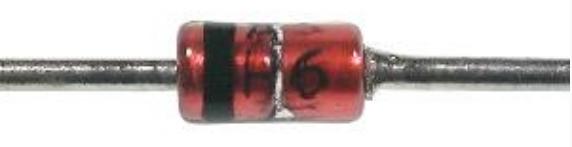
Zener diodes are diodes that have the characteristics to channel electrical current flowing in the opposite direction if the applied voltage overshoot “voltage damaged” (breakdown voltage) or “Zener voltage”. This is different from ordinary diodes which only transmits electrical current to one direction.

Diodes normally will not allow electric current to flow in opposite if fed-back (reverse-biased) below the breakdown voltage. If you exceed the limit of breakdown voltage, normal diode will be damaged because of excess electrical current that causes heat. However, this process is reversible if done within limits. In the case of rationing-forward (in accordance with the direction of the arrow), this diode will provide voltage falls (voltage drop) of about 0.6 Volt ordinary silicon diode. Voltage drop depends on the type of diode used.

A Zener diode has characteristics similar to ordinary diode, except that this tool is deliberately made ​​with a much reduced tengangan damaged, called Zener voltage. A Zener diode has a pn junction which has a heavy doping, which allows electrons to penetrate (tunnel) from the valence band p-type material into the conduction band n-type material. A zener diode is fed through a broken behavior will exhibit a controlled and will pass an electric current to keep the voltage falls to keep the zener voltage. For example, a 3.2 volt zener diode will show a fall in the 3.2 Volt voltage if given the supply and forth. However, because the current is not constrained, so that the zener diode is typically used to generate a reference voltage, or to stabilize the voltage for small flow applications.

A Zener diode is a type of diode that permits current not only in the forward direction like a normal diode, but also in the reverse direction if the voltage is larger than the breakdown voltage known as "Zener knee voltage" or "Zener voltage". The device was named after Clarence Zener, who discovered this electrical property.

A conventional solid-state diode will not allow significant current if it is reverse-biased below its reverse breakdown voltage. When the reverse bias breakdown voltage is exceeded, a conventional diode is subject to high current due to avalanche breakdown. Unless this current is limited by circuitry, the diode will be permanently damaged. In case of large forward bias (current in the direction of the arrow), the diode exhibits a voltage drop due to its junction built-in voltage and internal resistance. The amount of the voltage drop depends on the semiconductor material and the doping concentrations.

A Zener diode exhibits almost the same properties, except the device is specially designed so as to have a greatly reduced breakdown voltage, the so-called Zener voltage. By contrast with the conventional device, a reverse-biased Zener diode will exhibit a controlled breakdown and allow the current to keep the voltage across the Zener diode at the Zener voltage. For example, a diode with a Zener breakdown voltage of 3.2 V will exhibit a voltage drop of 3.2 V if reverse bias voltage applied across it is more than its Zener voltage. The Zener diode is therefore ideal for applications such as the generation of a reference voltage (e.g. for an amplifier stage), or as a voltage stabilizer for low-current applications.

The Zener diode's operation depends on the heavy doping of its p-n junction allowing electrons to tunnel from the valence band of the p-type material to the conduction band of the n-type material. In the atomic scale, this tunneling corresponds to the transport of valence band electrons into the empty conduction band states; as a result of the reduced barrier between these bands and high electric fields that are induced due to the relatively high levels of dopings on both sides. The breakdown voltage can be controlled quite accurately in the doping process. While tolerances within 0.05% are available, the most widely used tolerances are 5% and 10%. Breakdown voltage for commonly available zener diodes can vary widely from 1.2 volts to 200 volts.

Another mechanism that produces a similar effect is the avalanche effect as in the avalanche diode. The two types of diode are in fact constructed the same way and both effects are present in diodes of this type. In silicon diodes up to about 5.6 volts, the Zener effect is the predominant effect and shows a marked negative temperature coefficient. Above 5.6 volts, the avalanche effect becomes predominant and exhibits a positive temperature coefficient. In a 5.6 V diode, the two effects occur together and their temperature coefficients neatly cancel each other out, thus the 5.6 V diode is the component of choice in temperature-critical applications. Modern manufacturing techniques have produced devices with voltages lower than 5.6 V with negligible temperature coefficients, but as higher voltage devices are encountered, the temperature coefficient rises dramatically. A 75 V diode has 10 times the coefficient of a 12 V diode.

All such diodes, regardless of breakdown voltage, are usually marketed under the umbrella term of "Zener diode".
READ MORE - Zener diodes are diodes that have the characteristics to channel electrical current

ZENER DIODE TESTING


ZENER DIODE TESTING
The testing of zener diodes requires a variable dc power supply. A typical test circuit can be constructed, as shown in figure 4-19. In this circuit, the variable power supply is used to adjust the input voltage to a suitable value for the zener diode being tested. Resistor R1 limits the current through the diode. With the zener diode connected as shown in figure 4-19, no current will flow until the voltage across the diode is equal to the zener voltage. If the diode is connected in the opposite direction, current will flow at a low voltage, usually less than 1 volt. Current flow at a low voltage in both directions indicates that the zener diode is defective.


Zener Diode Tester
Here is a handy zener diode tester which tests zener diodes with breakdown voltages extending up to 120 volts. The main advantage of this circuit is that it works with a voltage as low as 6V DC and consumes less than 8 mA current. The circuit can be fitted in a 9V battery box. Two-third of the box may be used for four 1.5V batteries and the remaining one-third is sufficient for accommodating this circuit. In this circuit a commonly available transformer with 230V AC primary to 9-0-9V, 500mA secondary is used in reverse to achieve higher AC voltage across 230V AC terminals. Transistor T1 (BC547) is configured as an oscillator and driver to obtain required AC voltage across transformer’s 230V AC terminals. This AC voltage is converted to DC by diode D1 and filter capacitor C2 and is used to test the zener diodes. R3 is used as a seri- es current limiting resistor. After assembling the circuit, check DC voltage across points A and B without connecting any zener diode. Now switch on S1. The DC voltage across A-B should vary from 10V to 120V by adjusting potmeter VR1 (10k). If every thing is all right, the circuit is ready for use. For testing a zener diode of unknown value, connect it across points A and B with cathode towards A. Adjust potmeter VR1 so as to obtain the maximum DC voltage across A and B. Note down this zener value corresponding to DC voltage reading on the digital multimeter. When testing zener diode of value less than 3.3V, the meter shows less voltage instead of the actual zener value. However, correct reading is obtained for zener diodes of value above 5.8V with a tolerance of ± 10per cent. In case zener diode shorts, the multimeter shows 0 volts
READ MORE - ZENER DIODE TESTING

Jumat, 27 Mei 2011

Zener has a unique character a work in reverse bias, in contrast with ordinary diodes


Zener has a unique character a work in reverse bias, in contrast with ordinary diodes.


zener more doping at the junction P & N, so that the diode breakdown voltage can be more quickly achieved.


on ordinary diode breakdown voltage will occur hundreds of volts, while the zener breakdown can occur at rates of tens and units of volts.


zener has its own replacement series which consists of diodes, resistors, and voltage source who organized the series.


as a simple zener voltage regulator comprises a voltage source which in pairs with the series resistor & zener mounted parallel with the load.


its function is to keep the load voltage constant or nearly constant, although the load current and voltage source changes.
READ MORE - Zener has a unique character a work in reverse bias, in contrast with ordinary diodes

Changing the zener diode with ordinary photodiode


Changing the zener diode with ordinary photodiode

Common zener diodes in the know with some kind of voltage limits easily available in the market, the voltage range from 2.7 Volt varied from up to 160 volts, and even some manufacturers provide a diode voltage divider is up to hundreds of volts.
What if we are faced with a value of Zener diode that does not exist in the market ????,
First choice: try as hard as possible to find a match!?
second choice: find a suitable replacement (it took a pretty good )??!!
The third option: Using ordinary diodes to replace Zener diodes .......???!!!

for one condition most likely choice ketigalah, but how?
Simplified theory of diode ....( link)
It has an ordinary diode forward bias of 0.7 volts for the type of silicon and 0.3 volts for germanium types, then the use of forward bias is what we will apply as in (Figure 1), meaning that every one is equal to the ordinary diode zener diode 0 , 7 volts only just installed upside-down compared with the installation of zener diodes.
Then to make it a regular diode zener diode with a certain voltage obtained by stringing ordinary diodes in series in the can until the desired voltage, if you need a 2.1 volt zener diode then rangkailah ordinary diode with forward bias of 2.1 V: 0 , 7V = 3 (fruit), or by combining both the zener diode plus a normal diode forward dipanjar (image 2), as an example that we want to zener diode pairs was 13.4 volts, then add the zener diodes 12Volt with ordinary diodes by: (13 , 4V-12V): 0.7 V = 2 (pieces) are arranged series.
may be useful .......
READ MORE - Changing the zener diode with ordinary photodiode

Jumat, 13 Mei 2011

The circuit comprises transmitter and receiver


The circuit comprises transmitter and receiver, the cable under test linking the two. The transmitter is nothing more than a “LED chaser” the 4011 IC is wired as astable and clocks a 4017 decade counter divider. The 4017 is arranged so that on the 9th pulse,the count is reset. Each LED will light sequentially from LED 1 to LED 8 then back to LED 1 etc. As the 4017 has limited driving capabilities, then each output is buffered by a 4050. This provides sufficient current boost for long cables and the transmitter and receiver LED’s. The receiver is simply 8 LED’s with a common wire…read on.

The 4011 is a member of the 4000 Series CMOS range, and contains four independent NAND gates, each with two inputs. The pinout diagram, given on the right, is the standard two-input CMOS logic gate IC layout:
Pin 7 is the negative supply
Pin 14 is the positive supply
Pins 1&2, 5&6, 8&9, 12&13 are gate inputs
Pins 3, 4, 10, 11 are gate outputs

The truth table for one of the four gates is shown to the right. For more infomation about the NAND gate in general, see this module.

This chip is widely available, and usually comes in a DIL-14 or SOIC-14 package.

This chip is different in pinout to the TTL 7400, but can fulfill its function if the wiring is modified.
READ MORE - The circuit comprises transmitter and receiver

IC tester


IC tester
An Integrated Circuit tester (IC tester) is used to test Integrated Circuits (ICs). We can easily test any digital IC using this kind of an IC tester. For testing an IC, we need to use different hardware circuits for different ICs; like we need a particular kind of tester for testing a logic gate and another for testing flip flops or shift registers which involves more complication and time involved will also be more. So here’s an IC tester to overcome this problem. Unlike other IC testers, this is more reliable and easier since we don’t need to rig up different kind of circuits for different kind of ICs, each time we need to test them.

Unlike the IC testers available in the market today which are usually expensive, this IC tester is affordable and user-friendly. This IC tester is constructed using 8951 microcontroller along with a keyboard and a display unit. It can test digital ICs having a maximum of 24 pins. Since it is programmable, any number of ICs can be tested within the constraint of the memory available. This IC tester can be used to test a wide variety of ICs which includes simple logic gates and also sequential and combinational ICs like flip-flops, counters, shift registers etc. It is portable and easy to use.

The block diagram of the programmable digital IC tester is as shown in below. It consists of two 8951 microcontroller ICs, a 24-pin IC socket, a keyboard unit, a display unit and indicators.

To test a particular digital IC, one needs to insert the IC into the IC socket and enter the IC number using the keyboard and then press the “ENTER” key. The IC number gets displayed in the 7-segment display unit.

Four LEDs are provided as indicators. If the IC being tested is a logic gate, then each of the 4 indicator LEDs correspond to the 4 gates of the IC. In any other case wherein the inserted IC is not a logic gate, all the 4 LEDs work as a single indicator.
READ MORE - IC tester

Analog To Digital Converter


Analog To Digital Converter
There are little than two weeks until most of the telecasting stations of the cross in the North government make the lasting electric switch TV. Are you at the ready? There antemeridian, then , KNVN twenty-four and KHSL twelve will behavior a mental test aid you reply that inquiry.

Maryland Public Television said it will stop two of its broadcasts this calendar month video analog to digital converter and person them formatting as it prepares follow with a national authorization.

McCLAIN Perhaps you have detected about the alteration approaching in the new year. And no, it's not just about having a new corporate executive. If you ticker telecasting you likely have detected that on this message signals will electric switch from. Well, if you're like me, you likely have no thought what that agency or what benignant of impressive networks use convey our TVs. So we have through.
Aboriginal From Ic Time

Mediacom customers in Marshall and Calloway Counties will shortly be lining the aboriginal electric switch the all impressive. That agency about everyone will need container.

I've purchased container for my aged TV so that I'll be capable go on acquiring programs after the switchover from ic adjacent then. I was capable catch up container, TV and cablegram easy adequate, but I'm having problem calculation.

All The mental test is fix people for the electric switch telecasting at hour on this time. DTV will let stations of the cross offering built image, dependable choice and further transmission.
Casual Robert online
Telecasting All Audio Analog To Digital Converter Online

Help consumers fix for the closure of full-power telecasting signals and the passage telecasting on this all twenty-six Boston marketplace message telecasting stations of the cross and cablegram providers will take part in a day-long mental test of the new system on there.

QI've ready up TV and I get most of my section stations' broadcasts but not all audio analog to digital converter of them. Do any of these broadcasters have upgrades in shop for their signals?

Phillip Swann, CEO of TVPredictions.Com, will be online supply intelligence and proposal about televisions.
Casual Box

Q Will I be capable evidence programs off the aerial with my VCR after passage?

T he Federal Government has mandated that, after then , time, full-power telecasting stations of the cross will message in only formatting. This agency that telecasting sets, that get their impressive from at box large over the aerial broadcasts, may need add container in the aerial formation among the aerial and the telecasting ready. Free over the aerial agency acquiring the impressive from the aerial.

KMBC's Kris Ketz and Jerry Agresti entertainment how casual it can be catch up container for antennas.
For In Adc

All present fix viewing audience for the extremity of broadcasts.

Any delays in Canada's afloat passage from signals in time will consequence in adc Canadians turn American stations of the cross, Heritage Minister James Moore says.

The time get container is now, Federal Communications Commission Commissioner Robert M. McDowell said at a municipality hallway gathering day.
READ MORE - Analog To Digital Converter

Kamis, 12 Mei 2011

Various kinds of wires

Various kinds of wires

UTP ( unshielded twisted pair)

UTP cable or unshielded twisted pair cable is the cable used to create a computer network or cable network which contains four (4) pairs of wires that each pair is the twin with RJ-45 connector end.

Type / Type category UTP Cable / Unshielded Twisted Pair:
- Category 1: For a voice connection / phone line / phone
- Category 2: For the protocol LocalTalk (Apple) with data rates up to 4 Mbps
- Category 3: For the Ethernet protocol with data rates up to 10 Mbps
- Category 4: For 16 Mbps token ring protocol (IBM) with data rates up to 20 Mbps
- Category 5: For fast ethernet protocol with data rates up to 100 Mbps.

There are 3 types of UTP cables which are distinguished by category (cat): - UTP cat 3 for 10Base-T system (Standard Ethernet) with 10Mbps speed UTP cat-5 for the 100Base-T (Fast Ethernet) 100Mbps speed with UTP cat-5 Enhanced system for 1000Base-T (Gigabit Ethernet) with speed 1Gbps.Media Connection As media liaison between computers, we will need a cable. Since the STT Telkom network using a hub or switch, then the cable required is UTP (Unshielded Twisted Pair).
UTP cable has the following characteristics: - Connector in use at the end of the cable (any type / category) RJ45-UTP is composed of 4 pairs (pair) cable that was twisted (twisted) - 1 pair for Tx (send information) is on pin number 1 (TX +) & 2 (TX-) - 1 pair for Rx (receive information), namely the pin number 3 (RX +) & 6 (RX-) - 2 pairs of unused (Not Connected), interchangeable used to transmit electrical power (power over Ethernet) to distribute devices that exist at the end of the straight-wire UTP cable: if the end A is connected directly with the end B (TXA, TXB, RXA-RXB) - the cable cross: if the tip A cross-connected with the end B (TXA, RXB, RXA-TXB) - straight cables used to connect computers with hub (switch) - cross cable used to connect the hub (switch) with a hub (switch)-The maximum length of any other wearable UTP cable to distribute information is 50mtr

way utp cabling

UTP cabling to the RJ-45 port can not be used at random color sequence. For specific use, must use a different color sequence because it has become the rule. If the rule is ignored, then the connection will fail, or less than the maximum.

How to network cabling with UTP cable transmission medium is divided into two, namely:

- Straigh-Through

- Cross-Over

1. Straigh-Through

UTP cable with the installation of straigh-through is used if the relationship between:
· Port Ethernet / FastEthernet Router with Ethernet port located at the hub.
· Port Ethernet / FastEthernet Router with Port Ethernet / FastEthernet contained in the switch.
· Network adhapter installed on a PC with an Ethernet port on the hub.
· Network adhapter installed on a PC with an Ethernet port / FastEthernet at the switch.

2. Cross-Over

UTP cabling by means of cross-over is used if the relationship between:

- Switch to a switch.

- Hub to the switch.

- Hub to hub.

- Router with the router.

- NetPC with PC directly.


How to install RJ-45 connectors to the ends of UTP cable:
· Open and loose wrapping UTP cable using crimping pliers.
· Sort wire in accordance with international standards.
· Trim and flatten the ends of the wire 8 which has been sorted.
· Wire that has been sorted is inserted into the RJ-45 connector and make sure the order does not change.
· Make sure that the tip 8 wire is inserted to reach the deepest part (ends) RJ-45 connector.
· Lock RJ-45 UTP using crimping pliers.
· does the same at the other end of the cable.
· Check both ends of the cable connection using UTP cable tester


STP CABLE

Cable STP (Shielded Twisted Pair) is one type of cable used in computer networks. This cable contains two cable pairs (four wires), each pair twisted (twisted). Each cable is a cable with single core copper wire isolator. The four cable is wrapped with woven fiber cable that serves as a protective and grounding (shielded).

As the outer protective layer of insulator which is a leather cord. Ata this cable capable of transmitting up to 16 Mbps with a maximum distance of 100 meters.

Coaxial (Coaxial cable)

Coaxial cable is a copper wire that was covered by several protective where these protectors have the following functions:
Conductor, a single cable or fiber cable which is at the core of Coaxial cable. This section is part of the cable used for data transmission or a data cable.
Insulator in, an insulating layer between the conductor with a grounding, which also serves as a protective core cable (conductor).
Outer insulator, the insulator layer of the skin which is also a cable.

There are several types of coaxial cable used in computer networks, namely:
Coaxial RG-62A / U
Coaxial RG-58A / U (thinnet)
Coaxial RG-8 (Yellow Cable / Thicknet)

a. Coaxial cable RG-62A / U

Coaxial cable RG-62A / U Coaxial cable is a small, black with a core fiber cable. The size of this cable approximately 0:25 inch (6 mm). Coaxial cable is capable of transferring data at speeds reaching 2.5 Mbps, which is a low-speed low enough for a data communication within a computer network, but due to the ease of installation, the cables are widely used. This cable has a impedensi of 93 ohms and capable of transferring data at distances up to 1000 feet on a bus topology and reach 2000 feet in star topology using an active aid hub.

b. Coaxial cable RG-58A / U (thinnet) Baseband

Coaxial cable RG-58A / U is a small black coaxial cable similar to coaxial cable RG-62A / U. Coaxial cable RG-58A / U cable using a core of a single copper cable, but some are using fiber cable. This cable has a impedensi of 50 ohms. This cable is capable of connecting up to 30 network nodes (node) with a maximum distance reached 185 meters (607 feet).

c. RG-8 Coaxial Cable (Yellow Cable / Thicknet) Broadband

Coaxial Cable RG-8 is colored yellow, the cord is often called the Yellow Cable. Coaxial cable has a physical size two times larger than the coaxial cable RG-58A / U, ie a diameter of 13 mm (0.5 inch). However, this cable has a value equal to the independence of coaxial cable RG-58A / U, which is 50 ohms. Coaxial cable is capable of transmitting data up to a distance of 500 meters without repeaters or other enhancements

FIBER OPTIC

Fiber optics is one type of media data transfer in computer networks. At first glance looks like a cable, but unlike other cable because this medium to transfer data in the form of light. To use the fiber optic network card that has the required connector type ST (ST connector). The major advantage compared to fiber optic cable media is in terms of data transfer speed is quite high. In addition, the fiber optic cable capable of transferring data at a considerable distance, namely reach 1 mile without the aid of a repeater device. Fiber optimism also has advantages in terms of accuracy and security of data transmission. This is possible because optical fiber is not affected by interference from wild frequencies that may exist along the transmission path.
The weakness of existing fiber optic on the high level of difficulty in the installation process. Given that these media transmit data in the form of light waves, it can not install this medium in the path turns sharply or angled. If forced to turn, it should bend the curve. In addition it also should really avoid the possibility of physical pressure on the media.

Multi Mode Fiber Optic

This type of fiber optic light propagates from one end to the other place through some streaks of light.

Fiber Optic Single Mode

Fibre optic single mode or mono mode has a core diameter (core) is very small 3-10 mm, so that only one beam of light that can pass through

Network Interface Card (NIC)

Network Interface Card is an electronic board means that planted on any computer connected to the network. There are three things to be aware of suati NIC card type, protocol type and the type of cable supports. There are two types of cards, the PCI and ISA.
In terms of protocol, type of protocol which is currently the most widely used Ethernet and Fast Ethernet, the other an IBM Token Ring and ARCNet. In choosing the card must conform with the type of cable that have been / will be installed. If summarized the characteristics that determine the type of card is the combination of the following:
PCI (UTP)
PCI (UTP - BNC)
PCI Combo (UTP - BNC - AUI)
ISA (UTP)
ISA (UTP - BNC)
ISA Combo (UTP - BNC - AUI)
READ MORE - Various kinds of wires

Minggu, 08 Mei 2011

Transformer Types

Transformer Types
If the voltage output terminal is greater than the voltage that is changed, the transformer is used to function as Raising the voltage. Conversely if the voltage output terminal is smaller than the converted voltage, the transformer is used to function as lowering voltage. Thus, the transformer (transformer) can be divided into two, namely step-up transformer and step-down transformer.
Step-up transformer is a transformer that serves to raise the AC voltage.


This transformer has the characteristics:
a. the number of primary winding less than the number of secondary windings,
b. primary voltage is smaller than the secondary voltage,
c. strong primary current is greater than the stronger secondary flow.

Step-down transformer is a transformer that serves to lower the AC voltage.


This transformer has the characteristics:
a. the number of primary winding greater than the number of secondary windings,
b. primary voltage is greater than the secondary voltage,
c. strong primary current is smaller than strong secondary flows.

Ideal Transformer
Large voltages and currents depend on the number of transformer winding. Large voltage proportional to the number of loops. Greater the number of winding voltages generated greater. This applies to primary and secondary winding. The relationship between the number of primary and secondary windings with a primary voltage and secondary voltage formulated


Said transformer is ideal if there is no energy lost to heat, when the amount of energy into the primary coil equal to the amount of energy that came out in the secondary coil. The relationship between the voltage with a strong current in the coil primary and secondary formulated


If both sides are divided by t, obtained by the formula


In this case the factor (V × I) is the power (P) transformer.
Based on the above formulas, the relationship between the number of primary and secondary windings with a strong primary and secondary currents can be formulated as


Thus for an ideal transformer will apply the following equation.

By:
Vp = Primary voltage (input voltage = Vi) with units of volts (V)
Vs = secondary voltage (output voltage = Vo) with units of volts (V)
Np = number of primary winding
Ns = number of secondary winding
Primary current Ip = strong (strong input current = Ii) with the unit ampere (A)
Is = secondary current strength (strong currents output = Io), with units of amperes (A)
READ MORE - Transformer Types

TRANSFORMER

TRANSFORMER
At home maybe you're ever faced with the voltage issue, when you will turn on the radio that requires a voltage of 6 V or 12 V. Whereas the voltage supplied by PLN 220 V. Even generators produce very high voltage to reach up to tens of thousands of volts. The truth came home to live voltage 220 ​​V. How do I change the voltage? The instrument used to raise or lower AC voltage is called transformer (transformer). Transformer has two terminals, the terminal input and output terminals. Input terminals located on the primary coil. Output terminals located on the secondary coil. Voltage to be changed is connected with input terminals. Meanwhile, the results obtained by changing the voltage at the output terminal. The working principle of transformer applying electromagnetic induction events. If the primary coil energized AC, twist iron core will become a magnet coil (electromagnet). Because the AC current, the electromagnet is always a change of magnetic force lines. Change the line style will be shifted to the secondary coil. Thus, the secondary coil also changes the magnetic lines of force. That's what's causing the induction emf in secondary coil. Meanwhile, the induced current generated is a large AC current in accordance with the number of secondary winding.

Transformer there are three main parts, namely the iron core in layers, the primary coil and secondary coil. Primary coil connected to PLN as the input voltage (input) to be raised or lowered. Secondary coil connected to the load as the output voltage (output).
READ MORE - TRANSFORMER

APPLICATION electromagnetic induction

DC dynamo chart

AC dynamo chart

AC generator chart

APPLICATION electromagnetic induction
In electromagnetic induction deformed energy of motion into electrical energy. Electromagnetic induction is used in generating electricity. Generating electrical energy is applied electromagnetic induction generator and dynamo. In the generator and the armature coils and magnets there. Coil or the magnet that spins leads to changes in the number of lines of magnetic force in the coil. These changes caused the emf induced in the coil. Mechanical energy provided by generators and dynamos converted into rotational energy. That caused the induction emf generated continuously with a periodic repeating pattern
1. Generators Generators are divided into two, namely generators direct current (DC) and alternating current generator (AC). Both the AC generator and DC generator rotate the coil in the magnetic field fixed. AC generator is often called the alternator. The electric current produced is alternating current. AC generator characteristics using double ring. DC current generator, the resulting flow of direct current. Characteristic of DC generator using a split ring (commutator). Thus, the AC generator can be converted to DC generator by replacing a double ring with a commutator. An AC generator coil rotates between the poles is not a kind of two magnets facing each other. The two poles of a magnet will generate a magnetic field. The two ends of the coil is connected with carbon brushes contained in each ring. Coil is part of a rotating generator (move) is called the rotor. Permanent magnet generator part that is not moving is called the stator. How do generators work? When the coil is parallel to the direction of the magnetic field (forming an angle of 0 degrees), has not happened and there is no electric current induced emf (see Figure 12.2). When the coil rotates slowly rising currents and emf to the coil to form an angle of 90 degrees. At that time the position of the coil perpendicular to the direction of the magnetic field. In this position of strong currents and emf induction showed a maximum value. Furthermore, the coil continues to spin round, currents and emf dwindle. When the coil to form a 180 degree angle position of the coil parallel to the direction of the magnetic field, the induced emf and induced current becomes zero.

The next round of the coil current and the voltage starts to rise again in the opposite direction. At the time of forming an angle of 270 degrees, occurred more coils have current perpendicular to the direction of the magnetic field. In a strong position and emf induced currents showed a maximum value again, but different direction. The next round of the coil, current and voltage down gently until it reaches zero and the coil back to its original position until entuk memb 360 degree angle.
2. Dinamo Dinamo divided into two, namely, armature direct current (DC) and magneto alternating current (AC). The principle of working together with the generator armature coils which rotate in a magnetic field or rotating magnet inside the coil. A rotating part called a rotor dynamo. Dynamo that is not moving part called a stator. The difference between the DC dynamo by dynamo AC lies in the ring is used. In direct current dynamo using a ring that split into two so-called split ring (commutator). This ring allows the electric current generated in the outer circuit of direct current Dinamo even within his own dynamo produces alternating current. Meanwhile, on an alternating current dynamo using a double ring (two rings). Tools of alternating current electricity generation of the simplest is a bicycle dynamo. Power that is used to rotate the rotor is a bicycle wheel. If the wheel rotates, the coil or the magnet rotates participate. Consequently, the resulting emf induced on the ends of the coil and electric current to flow. The faster the movement of a bicycle wheel, the faster the magnet or the coil rotates. The greater the induced emf and electric current generated. If connected with the lamp, the bright lights. Emf induced in the armature can be enlarged in a way round the wheel is accelerated, using a strong magnet (large), the number of winding reproduced, and use a soft iron core inside the coil.
READ MORE - APPLICATION electromagnetic induction

Occurrence Cause Induction emf


Occurrence Cause Induction emf
When the magnetic north pole rod driven into the coil, the number of line styles contained in the magnetic coils multiply. Increasing the number of lines of force raises emf induced at the ends of the coil. Induction emf generated causing an electric current to flow to move the needle galvanometer. Direction of induced current can be determined by watching the direction the magnetic field caused. When the magnet entrance, lines of force in the coil increases. As a result the magnetic field induced flow results are reducing lines that style. Thus, the coil end is the north pole so that the direction of induced current as shown Figure 12.1.a (remember again how to determine the poles of the solenoid).

When the north pole of bar magnet is moved out of the coil, the number of magnetic lines of force contained in the coil is reduced. Decreasing the number of lines of force also creates an emf induced in the coil ends. Induction emf generated causing an electric current to flow and move the needle galvanometer. Similarly, when the bar magnet into the coil. when the magnetic lines of force in the coil exit is reduced. As a result the magnetic field induced currents are the result of adding the line that style. Thus, the tip, the coil was a south pole, so that the induced current direction as shown Fig 12.1.b. When the north pole of bar magnet is in the coil, the number of lines of magnetic force in the coil does not change (fixed). Since the number of lines of force remain, then at the ends of the coil does not occur emf induction. As a result, there is no electricity and no moving needle galvanometer. So, emf induction can occur at both ends of the coil if the coil there is a change in the number of lines of magnetic force (magnetic flux). Emf arising from a change in the number of lines of magnetic force is called emf induced in the coil. An electric current induced emf generated is called induced current. Occurrence of events and induction emf induced currents due to changes in the number of lines of magnetic force is called electromagnetic induction. Try to specify how to treat the magnet and coil for induction emf arises?
2. Factors that Influence the big Actually Induction of small emf emf induction can be seen in the size of the deviation angle galvanometer needle. If the angle deviation of the galvanometer needle, induced emf and induced current generated large. How do I enlarge the emf induced? There are three factors that influence the induction emf, namely: a. magnet movement speed or velocity changes in the number of lines of magnetic force (magnetic flux), b. winding number, c. magnetic field
Exercise
READ MORE - Occurrence Cause Induction emf

Modulasi OT426


Modulasi OT426
Until the mid 80'an, AM mode still dominates the 80m band radio communication. AM transmitters are easy to make, and very suitable for beginners who want to explore the techniques of radio communication. With the enactment KEP-065/OP/KU/2009, the AM mode can be reused by the level of alert. Allocations in the 3550-3560 MHz frequency (10khz ???), with audio bandwidth not exceeding 6Khz. The easiest way to make the AM mode, is to use a transformer modulators (series modulator). Used to be very easy to find transformer capacity OT426 from 10W to 100W. But now the heart of an AM transmitter is already difficult to find. The alternative? using a transformer in the market? yes, the transformer power supply ...... Alternative model 1: Using 1 pc power supply transformer secondary with identical. Transformer power supply that is used must have two identical secondary, eg 0-12V, 0-18V, and so on. If the final transistor taking a current of 1A with a voltage of 12V, then the transformer power supply that is used must also have a secondary with 1.5x current 1A = 1.5A and 12V voltage. 1.5x multiplier, because the assumption of additional power modulators for half of the power needed by the final transistor transmitter. Capacitors for 10000uF, used for amplifier protection against wild currents. BE CAREFUL with its primary section (0-110-220), nyetrum .... Alternative model 2: Using 2 pieces of transformer power supply. If you are having trouble finding an identical transformer with the secondary, you can use 2 pieces of the primary transformer (0-220V) connected to each other. Secondary one associated with the final transistors, other secondary modulator. BE CAREFUL with its primary section (0-110-220), nyetrum .... Alternative model 3: Using 2 pieces of transformer power supply that are far apart. Sometimes we need a separation of part of his transmitter with audio, with 2 of the transformer, not a problem, stay connected with cable twinpair. In this way, the transmitter can be separated with an audio modulator of 10m-100m, without fear of losing power in its audio amplifier. BE CAREFUL with its primary section (0-110-220), nyetrum .... Using the transformer modulator, is a way of generating the most simple AM ​​mode is made (for beginners though). Other types of series modulator is to use transistors (not transformer). Series modulators suitable only for low power. Generation cara2 AM other than the above is to use PWM (pulse width modulation), PDM (pulse duration modulation), and so forth. In principle, the audio is inserted into the OWN / PDM, so that the output voltage will move from half Vcc to Vcc in sync with the audio amplitude (linear). Both are commonly used as modulators for AM transmitters powered.
READ MORE - Modulasi OT426

How to make a transfomer


How to make a transfomer (transformer):
First: Determine the transformer VA:
For example: We will create a voltage transformer with 2 x 32 volt, 5 Ampere. Secondary Power: 2 x 32 x 5 = 320 VA. Primary Power: 1.25 x 320VA = 400VA.

Second: Calculated nuclear weight:
Nuclear Weight (grams) = 1.5 x the primary x 1.5 x 7.8 = 400 x 7.8 = 4680gr = 4.68 kg.

Third: Calculate the iron core.
b = root 3 of ((1.5 x primary power) divided by 9.9) = 3.92 cm (4cm rounded).
h = b / 0.6561 = 6cm.
Cross-sectional area (A) = b x h = 4 x 6 = 24 cm2.

Fourth: Determine the number of coils per volt: 50 / A (cross-sectional area) = 50/24 = 2.08 = 2lilit / volt. * Fifth: Determining Copper Diameter: 0.7 x root 2 of the current.
"Diameter of secondary roots = 0.7 x 5 = 1.56 mm. Diameter of primary root = 0.7 x 1.82 = 0.94 mm. "1.82 = 440va/220volt.

if transformer toroid models have no engines roll so hard. with a manual like embroidery or crochet. toroid cool too hard to find in accordance with the size you want.

if the model more easily roll their own box, tool roll which many distinguished sales manual.
like this.

I just roll transformer calculation is simple:
* volt x 2 + 10%
example:
* 220v x 2 + 10% = 440 + 10% = 484 rolls.

I used to Koker pcb with copper I remove the first layer.
designs like the letter I and the letter O box, adjustable size with cool that will be used.
READ MORE - How to make a transfomer

Power Inverter


This power inverter circuit will provide a very stable “Square Wave” Output Voltage. Frequency of operation is determined by a pot and is normally set to 60 Hz. Various “off the shelf” transformers can be used. Or Custom wind your own for best results.

An inverter is an electrical device that converts direct current (DC) to alternating current (AC); the converted AC can be at any required voltage and frequency with the use of appropriate transformers, switching, and control circuits.

Additional MosFets can be paralleled for higher power. It is recommended to Have a “Fuse” in the Power Line and to always have a “Load connected”, while power is being applied. The Fuse should be rated at 32 volts and should be aproximately 10 Amps per 100 watts of output. The Power leads must be heavy enough wire to handle this High Current Draw! appropriate Heat Sinks Should be used on the RFP50N06 Fets. These Fets are rated at 50 Amps and 60 Volts. Other types of Mosfets can be substituted if you wish.

There ARE Limitations! I have had numerous requests for an Inverter for 1000 watts and Even MORE. Sorry I Don’t feel this is Practical. At 1000 Watts and operating from a 12 Volt Source, the Input Current will be close to 100 AMPS. That would Require a HUGH Size of a Primary Wire.

Related posts:
Power Inverter : Simple High Power Inverter 12V to 110V 2N3055 This is Simple High Power inverter by 2N3055 circuit.

Stand Alone solar panel inverters function to change direct current (DC) from a battery to Alternating Current (AC). Stand alone inverters, which range from around 100 watts to as much as 8000 watts, are used to power a vast variety of personal or small business projects. Lower watt stand-alone inverters are often used to power laptop computers, whereas high-watt stand-alone inverters could be used to help power an entire household. In order to calculate what class of inverter you need for use with your solar panel, you will first have to determine the maximum sum of all of the Alternating Current loads in your project (or home).
How to calculate the wattage you need from your stand-alone solar panel inverter

AC_LoadDryer
+AC_LoadLaptop
+AC_LoadIron
=Total AC Load

This is the wattage you need from your stand alone solar panel inverter.

You can usually find the wattage rating on your home appliances by checking the power cable. The sum of these wattage ratings is what you need to determine the wattage you need from your solar panel stand-alone inverter.
READ MORE - Power Inverter

Sabtu, 07 Mei 2011

STEPS refit TELEVISION

STEPS refit TELEVISION


Pictured above is an example of how to dispose of the remaining voltage on the flyback letterhead.

In a television repair, television needs to be removed when the machine is then used to dispose of the remaining voltage on the flyback and tube headers (like the example above). Although the TV is totally dead but the letterhead and the flyback voltage of the tube is still a fairly large store.

Pictured above is an example of how to safely remove the header of the flyback.

Although stress has been wasted, if you want to remove the header of the flyback it to be safer to use tespen. If still there is little tension left over it will be wasted on such tespen lamp.

Sample of RGB block release

Pictured above is an example of removing the RGB part of the cathode tube. Which white color is the cathode socket. You must be very careful when removing the socket, because if it does not really way off can cause a broken neck or broken tube cathode tube.
The figure below is a sample machine JVC brand TV old model that has been removed from the tube to be repaired in a condition more freely Total.Agar Dead in refit when flipping through the machine.


Example Machine released from Tube TV


Part Power Supply / Regulator

Pictured above is an example of the power supply / regulator long. You JVC TV machine must know the names of the components and functions and how to work the regulator them. With us you will more easily in engine repair TV. This origin can not measure the components of dead or living alone . But it must be a little work to analyze the sequence of the regulator. Next are the steps off the TV repairman this total. Step I type in sequence, starting from the open box to finish refit. The goal for technicians with beginners who are just starting to learn more understand. For television repair technician who was a senior my blog probably is not useful. So please understand for technicians who already senior. thanks.
Steps:
First, open the box lid rear. If television fix this situation the total dead, better off alone from the television machine tube. As example in the picture above. Facebook more freely if flipping through television them. Besides machine, it will be easier in checking components and measurement of risk is not safe voltage. The jar also hit hard objects that accidentally during repair, such as screwdrivers, pliers or tools lain.Hati careful removing machines, cables associated with the tube must be removed first, such as letterhead flyback (do not kop held before discharge voltage). And do not immediately released, first remove the voltage that is still stored in the header of the flyback, which is usually still there. Way multitester take one cable, then connect the plug to ground tube. Multi plug that taper to stick to flyback. Then letterhead will be wasted in the voltage remaining in the header and tube them. After wasted then they will head off from the tube by using tespen. Why using tespen? The goal, if still a little tension there, it will be wasted on tespen lights, you are more safe. After header apart, then release a series of RGB blocks stuck in the neck tube, very careful in removing the socket, because if the leg is the cathode tube until broken or cracked glass tube neck, then you replace it tube. Look at example above.
The second step is to clean the dust that is clean and also clean the dirt on the pcb tracks by using the old toothbrush and a quick thinner evaporates or it could be alcohol. Way, thinner or alcohol drops on a toothbrush and a pcb which will cleaned, then scrub with a brush to clean the dirtdirt. Why pcb to be cleaned? The goal is for the cracked solderan looks and ease of checking or soldering. Next first transistor is off existing horizontal panel flyback. For avoid refrigeration near your negligence if the machine if the machine life. Because television live television, it will inject high voltage flyback at 20-25KV. You try imagine if exposed to stress for it. But if Transistors panel has been removed then you've safe. Because this is important, I remind only. But you do not continue to be afraid, later after reading this guide youscared. So a technician do not be afraid that your important careful and always watch where the letterhead flyback each will try to turn on the television machine, not to lie above / below machine. Letterhead flyback far along they will have to put the header and the cable is facing up or put in a glass just more safe (position if Tr panels are mounted horizontally, if not installed it does not matter).
The third step is to check the voltage is 220V and 220V voltage fuse. If normal & normal fuse, then check the voltage at 400VDC Elko, if no voltage then check diode diode rectifier bridg or 4, maybe something is broken.
Step four, if the voltage at 400V Elko already exist (the voltage is only about 250-300VDC, not exactly 400VDC) and then measuring the secondary voltage of 110-115 VDC.
If the voltage is 110VDC not exist, then we check one by one region of secondary power supply only. Or you do soldering on the first anniversary of suspected, has not come out and try turn. If B + voltage is 110V, then do check the components one by one in the area of ​​secondary power supply.
For security reasons if you fix the power supply, get used to horizontally disposed first transistor panel, above the already described. This is important to avoid your negligence, because if the power supply is on, and a horizontal oscillator output is also live up to the flyback will inject high voltage 20-25KV .
Unplug / suction formerly solder B + in the legs flyback that has to do with the Elko B + 160v for not burdened by the flyback in repairing power solder supply. If not removed nor anything, will not spray voltage flyback transistor during the horizontal bar has not installed. But p. are important too, because what? To find out leg B + flyback konslet or not. Then konslet, then the B + voltage from the power supply will turn off after connected to the foot of B + flyback. Then directly you know that the flyback is a short-circuit.
If the voltage B + is not out, then the next step before measuring the active component, such as the transistor Tr {}, all the measured one by one, if you find something is broken then replace it new.
Ninth step, if the B + power supply has not come out as well but all normal transistors, then check out these Zener diode Zener 110V. Dioda great shape, like a diode 3A.Nah .., this zener usually drop out, because this is a zener diode barrier B + 110 VDC.
Tenth step, eg B + has not come out as well, whereas active components such as transistors, diodes all have been checked normal. Then check resistors {R}, usually leading R Transistor Base Panel of Elco 400V power supply cut off, worth about 100k-150K is 2 pieces , replace both Resistor.
Power supply on television for his console / transistor output transistors do not all wear, some wear is STR or SMR.STR IC Integrated Circuit} {but it also transistor 2 pieces and there Resistor. If STR is damaged then the R around usually damaged, broken or elastic, if we replace the STR, then all the work for STR R perfect. Well replaced, if there is a short-circuit televisions turned on electricity directly or down the power supply must be broken, can be a short-circuit or transistor STR panels damaged / konslet or from bridg konslet diode, can also konslet 400V mylar capacitor.
If the secondary voltage exists, then you measure and adjust the trimpot B +, the average voltage of 110-115 Vdc.Dan measure the output voltage B + and other appropriate standards.
Terms for the machine must be able to live television pwr supply voltage, horizontal oscillator, driver horiz, horiz output, B + vertical and vertical output and heater voltage, screen voltage (G2), video output and voltage TEG RGB.Diantara these parts The most important role is the power supply and the Horizontal, the second part of this is like the heart, have to live first, then new, just other.
How many tension between the parts they will be, the following explanation:
-Power supply: 110V-115Vdc
Horizontal-oscillator: 8-12VDC TEG for IC {osc}
Horizontal-driver: 50Vdc at the foot of collector Tr {horz} drivers
Horizontal-output (H-Out): 0.2 VDC {osc to the base of the IC driver Ho} Tr
TR-base horizontal output: 0.5 VAC
Vertical-IC: 24VDC TEG B + IC {vertical tsb}
Vertical-output: 12V-16Vdc {from IC to the deflection Vert Vert}
-Heater: 6VAC
-Screen (G2): 250V-500Vdc
Cathode-RGB {}: 90V-125Vdc
-Video output: 180Vdc} {from flyback
-Program: 5Vdc {TEG B + for the IC program}

If voltage from the power supply all the normal, the next important is the need to turn part of first. Start horizontal oscillator, driver and output horizontal. For other parts later. You see the data on the thirteen steps, adjust the quick and practical voltage. In , directly measuring the voltage at the base of horizontal output transistors (of the transformer TR IT bound horizontal base out) there should be about 0.5 VAC, very small (but must exist). If the base voltage is already there means they have been living machine, and you do not need to measure the start of the oscillator.
If the voltage of the transformer TR IT that led to the horizontal base out there, then the machine is not possible to live television, then you just sort checking. Start of the oscillator until the output voltage existing horizontal. If means the machine has been able to live TV and pairs of horizontal output transistor released earlier, but measured the first transistor is good or not and the machine is ready to try TV.

Quite clear from the above summary of the total dead TV deal, ranging from checking the power supply to turn on the TV, then you are able to service the TV itself without asking the help of other workshops.
READ MORE - STEPS refit TELEVISION

Electronic Basics Tutorial


Electronic Basics Tutorial:
Various kinds of electronic components
Transistor
How to Measure Transistor
Condenser / capacitor
How To Measure Capacitor Elco
Measuring Capacitor Ceramic / mylar
How to Read The mylar & Ceramic Capacitor
Resistors
Resistor Color Table Regular
Metal Resistor Color Table
How to Read Resistor Ordinary
How to Read Resistor Metal
Diodes
Sort sorts diode
How to Measure Diodes
How to Measure Diodes Kuprok
Transformer / Transformer
How to Measure Transformer
Transformer Process
Adaptor / Regulator
Examples of Simple Series Regulator
Series & Parallel circuit

List the contents of the above is the contents of all the tutorials that I made ​​and accompanied by an explanation with complete. How to measure voltage, repair steps, how to repair with right, how to measure the tube, how to measure the components and so you can see yourself with a list contents. All of the pictures. Can you prove.
Below is one example of the contents of the tutorial on the first page, if you want to learn more complete and clear can the message directly to this. Blog is made ​​in my original photo-photo own. In examples in this blog is my original photo and sentence explanation The original also my description own. Because results based on experience.


Color TV Gb.1A.Skema

Gb.1B.Skema Part Color

Black & White TV Gb.2.Skema

The following is a description of the function of each part:

Antenna: serves to capture the RF signals from television transmitters.
Tuner: functions to select the wave transmitter that will be accepted.
Inside there are tuner RF amplifier, mixer and oscillator.
RF amplifier duty to choose the transmitter to be received and then given to the mixer.
Mixer eventually produce a new frequency, then filtered into 2 frequencies are out of 38.9 MHz and 33.4 MHz.
The frequency of 38.9 MHz image carrier is frequency
The frequency of 33.4 MHz is the frequency of the sound carrier.
The two frequencies are then forwarded to the video IF amplifier.
Video IF: serves to strengthen the signals received from the mixer, then forwarded to the video detector.
Video detector: function detects image signals and sound then forwarded to the video picture carrier driver. Signal out image signals are detected up to a frequency 15 KHZ-5 MHZ, the sound carrier signal is detected to exiting new sound carrier signal 5.5 MHz (FM).
Video driver serves to separate the voice carrier signal, the image signal and the signal sincronisasi.
Image signal transmitted to the video output.
Voice signals transmitted to the sound IF amplifier.
Synchronization signal is transmitted to the sync separator.
Video output signal function reinforce the image and then forwarded to the cathode tube.
Sound IF amplifier serves to strengthen the voice signal is then forwarded to the FM detector, the detector detects the FM signal frequency of 5.5 MHz to live audio, audio amplifier and then to continue to loudspeaker. For the sound IF to this audio amplifier such as booster amplifiers usual.
Syncronisasi separator serves to adjust the images transmitted from the transmitter.
Vertical oscillator function generates a frequency of 50 Hz and then forwarded to the output drivers and vertical vertical, next to the vertical deflection and vertical deflection is open the image vertically (top down).
AFC function corrects the horizontal frequency of 15.625 KHz and forwarded to the horizontal oscillator.
Horizontal oscillator functions to generate frequency 15.625 Khz and then forwarded to the driver and then horizontally to the horizontal output next to the horizontal deflection and horizontal deflection is open picture horizontally (left-right).
Horizontal output also generates about 10-20 kv high voltage to the anode tube.

READ MORE - Electronic Basics Tutorial

crt tv solutions damaged


crt tv solutions damaged

Perhaps we often hear people say "oh TV broken jug." The question that arises then, is it true they were damaged tube TV. The answer may be yes can not.
Sometimes we look at our screen is not intact (depressed / or folding) so that there is a black section at the top or bottom, sometimes if the damage is severe there is only a horizontal line across our TV screens. People who do not know anyone diagnose the tv is broken jug. This is wrong. Our TV was not damaged but the jar is broken on the vertical synchronization.
Then there are also depressed the side of the screen left or right. It's also not because of damage to the tube. For this damage there is some possibility that corrupt: could the horizontal section, Fly back transformers, power supply, or perhaps only the electrical voltage in your house are too ngedrop.
Then the trapezoidal-shaped screen or a depressed left, right, top and bottom. Typically for this damage often occurs due to the deflection coil short / shorting because of peeling layers of this email. Damage if left unchecked will spread to the horizontal section and other parts or even worse will make us die tv total.
Subsequent damage is the dominant color tv looks a particular color or no color that is unusual or loss of a particular color. For this damage could be a tube television is truly broken. but it's good we simply diagnose own destruction if we understand a little electronics knowledge.
To damage this color, things to do is look at what the dominant color or colors are missing. (Red, green, blue) because it is technically a color tv is a merger of the three elements of color.
Once we know what color is missing, we can take that next step is to try to improve or to call a service person if we are not able to fix it.
The question may be how to find the damage or repair this damage?
Here I will try to write a little trouble shooting on this type of damage is simple:
after we open the casing, the rear of the tube there is a small PCB and attached to the rear tube. It is from the amplifier PCB color. usually damage often occur there. The first step you can do is clean the surface of the PCB with tiner, and then do the strengthening soldiran there by way of re-soldering the legs of the components that exist there. soldiran cracks that are not seen clearly by eye color can result in damage earlier. and sometimes with steps that can overcome the damage. Nb: for TV brands National / Panasonic usually with this step can not recover damages even though the initial damage is the release soldiran. steps to take is replace the transistor amplifier in the PCB color (red, green, blue) all three at once.
If after the re soldir but color is still not normal, is now our turn to check it true that our TV tubes are damaged or indeed any other damage. The way is simple.
Take our multi-meter cable, can be a black or a red. Then plug one end on the ground of our TV (chassis), then turn on the TV, then one end of the cable before we plug it into a cathode tube feet on the small PCB earlier. There are 3 cathode there, red, green, and blue. Usually written in the PCB cathode KR to red (red), KB to the blue cathode (blue) and KG for cathode green (green). Notice the screen changes when we do this step. The color screen will be the dominant red color when we'd plug in a red cathode, as well as for other colors.
If the colors on the screen does not change when we plug the cable into the cathode, are suspect damage to the tube (screen) from our tv. Although it could happen CRT socket of the pin loose.
When the diagnosis we express our TV tube is not damaged, we can make small repairs to replace a active / passive in the little PCB. Typically a transistor that is often damaged. If we can not or are afraid to do so, we can call a service person. with a light lunch we had our diagnosis can be denied if the technician / handyman service we declare tube / tv screen is broken.
READ MORE - crt tv solutions damaged

Kamis, 05 Mei 2011

A micro-controller 24FC1025 EEPROM is a single integrated circuit


A micro-controller 24FC1025 EEPROM is a single integrated circuit, commonly with the following features:
central processing unit - ranging from small and simple 4-bit processors to complex 32- or 64-bit processors
volatile memory (RAM) for data storage
ROM, EPROM, EEPROM or Flash memory for program and operating parameter storage
discrete input and output bits, allowing control or detection of the logic state of an individual package pin
serial input/output such as serial ports (UARTs)
other serial communications interfaces like I²C, Serial Peripheral Interface and Controller Area Network for system interconnect
peripherals such as timers, event counters, PWM generators, and watchdog
clock generator - often an oscillator for a quartz timing crystal, resonator or RC circuit
many include analog-to-digital converters, some include digital-to-analog converters
in-circuit programming and debugging support.

An external EEPROM is useful when trying to store data. In addition to storing much more data than is available on the 18F4520 PIC, an EEPROM stores the data even when power is removed and can then be collected at a later time. Storing large amounts of data over time is especially beneficial once communication can be made between the PIC and Matlab. Using the serial function in Matlab, the data can be obtained and then analyzed.


In this project, we used the PIC to log data from an analog input onto an EEPROM and then later sent the data back from the EEPROM to Matlab to plot. For our lab, we worked with a 24FC1025 EEPROM whose data sheet can be found here. Additionally, we established serial port connection between the PIC microcontroller and Matlab using the RS232. Our project also made use of two buttons. The first button tells the PIC to begin collecting data points from the analog input and storing the data onto the EEPROM. The second button tells the PIC to send the data from the EEPROM to Matlab.

Diagram for interfacing a 24FC1025 EEPROM to the 18F4520 PIC. Below the diagram are photos of the circuit layout.


For more details regarding pin assignments for the EEPROM, see here.


/*
Upon pressing button 1, take 1000 data values from AN0 and save to EEPROM
Upon pressing button 2, wait for Matlab response, then output all data points from EEPROM
*/

#include <18f4520.h>
#fuses HS,NOLVP,NOWDT,NOPROTECT
#use delay(clock=40000000)
#use i2c(MASTER, FAST, SCL=PIN_C3, SDA=PIN_C4, FORCE_HW) // use hardware i2c controller
#use rs232(baud=9600, UART1) // Set up PIC UART on RC6 (tx) and RC7 (rx)
#define EEPROM_WR 0xA0 // Define initial EEPROM write address block (See EEPROM data sheet)
#define EEPROM_RD 0xA1 // Define initial EEPROM read address block (See EEPROM data sheet)

int button1, button2, data_rx = 48; // Initialize variables
int16 i, temp, value, address = 0, data;

void seq_write(int16 address, int16 data)//Writing to the EEPROM function
{
i2c_start();
i2c_write(EEPROM_WR);
i2c_write(address>>8);
i2c_write(address);
i2c_write(data);
i2c_stop();
delay_ms(5);//Delay time needed in order to allow EEPROM to write data from buffer to memory sector
}

int16 seq_read(int16 address)// Reading from the EEPROM function
{
i2c_start();
i2c_write(EEPROM_WR);
i2c_write(address>>8);
i2c_write(address);
i2c_start();
i2c_write(EEPROM_RD);
value = i2c_read(0);
i2c_stop();
return(value);
}

void main() //Main Function
{
setup_adc_ports(AN0); //Setup Analog Inputs
set_adc_channel(0);
setup_adc(ADC_CLOCK_INTERNAL);

while (TRUE)
{
button1 = input(PIN_D0); // Button one is pressed when the user wants to write to the EEPROM
button2 = input(PIN_D1); // Button two is pressed when the user wants to read from the EEPROM and send the data to Matlab

if (button1 == 1) {
output_high(PIN_D0);//LED is turned on to show that writing to the EEPROM has begun
address = 0x00;
for (i=0; i<1000; i++){
data = read_adc();//Read in data from analog input (In this case it was attached to a function generator)
seq_write(address, data); // Send data from analog input to write function
address++; // Increment up the address location on the EEPROM for the next time it writes something
}
output_low(PIN_D0); // LED is turned off to show that writing to the EEPROM is complete
}

if (button2 == 1) {
address = 0x00; // start at the first address location
while (data_rx == 48) {
output_high(PIN_D1);
if (kbhit()){
data_rx = fgetc();
temp = seq_read(address); //read data from adress location
printf("%lu \r",temp); // sends data to serial port
address++; // increment up the address so it can read from the next data sector
}

button1 = input(PIN_D0);
if (button1 == 1){
output_low(PIN_D1);
data_rx = 48; // 48 is the ASCII Code for integer '0'
delay_ms(500);
break;// Basically break from this loop if user presses the first button
}
}
data_rx = 48; // 48 is the ASCII Code for integer '0'
}
}
}
Matlab Code
%Brandon Robins, Neil Tiwari and Jenny Yong
%serialcom.m
%Construct serial port object, then send confirmation for EEPROM data

%deletes any serial port objects that exist in memory
delete(instrfind)
%Define serial COM Port
s1 = serial('COM8');
%Open the com port
fopen(s1);

set(s1,'Terminator','CR');

%Length of data points to be retrieved from EEPROM
final = 1000;

%For loop for retrieving data from the EEPROM
for ii = 1:final
if ii ~= final
%Send EEPROM "0" to signal that a data point should be sent
fprintf(s1,'%s','0')
%Get data point from eeprom
x(ii) = fscanf(s1,'%g');
else
%At the very last data point send EEPROM "1" to terminate the
%sending process
fprintf(s1,'%s','1')
% Get final data point from EEPROM
x(ii) = fscanf(s1,'%g');
end
end

%Close serial port
fclose(s1);
%Delete serial port object
delete(s1);
%Plot retrieved data
plot(x)

To operate the EEPROM, PIN1 and PIN2, A0 and A1 are set to ground. PIN3, A2 is connected to high for normal operation. PIN4, Vss is used to ground the chip. PIN5, SDA is the serial data line and is connected to RC4 (PIN23) on the PIC. PIN6, SCL is the serial clock line which is connected to RC3 (PIN18) on the PIC. PIN7, WP is the write protect line. For our purposes, we set PIN7 to ground to disable this function and allow us to rewrite our data onto the EEPROM. PIN8, Vcc is connected to high to power the chip.

In order to connect our PIC to Matlab, we use the RS232. As mentioned here, we connect the black wire to ground, the orange wire to pin 26, RC7 and the yellow wire to pin 25, RC6.

Additionally, we used two buttons connected to digital inputs on the PIC which dictate when to collect and store data and when to send the data to Matlab.

code matlab
%Brandon Robins, Neil Tiwari and Jenny Yong
%serialcom.m
%Construct serial port object, then send confirmation for EEPROM data

%deletes any serial port objects that exist in memory
delete(instrfind)
%Define serial COM Port
s1 = serial('COM8');
%Open the com port
fopen(s1);

set(s1,'Terminator','CR');

%Length of data points to be retrieved from EEPROM
final = 1000;

%For loop for retrieving data from the EEPROM
for ii = 1:final
if ii ~= final
%Send EEPROM "0" to signal that a data point should be sent
fprintf(s1,'%s','0')
%Get data point from eeprom
x(ii) = fscanf(s1,'%g');
else
%At the very last data point send EEPROM "1" to terminate the
%sending process
fprintf(s1,'%s','1')
% Get final data point from EEPROM
x(ii) = fscanf(s1,'%g');
end
end

%Close serial port
fclose(s1);
%Delete serial port object
delete(s1);
%Plot retrieved data
plot(x)

READ MORE - A micro-controller 24FC1025 EEPROM is a single integrated circuit